What Is a Fluid Coupling and How Does It Work?
A Fluid Coupling transfers rotating power through moving liquid rather than a direct mechanical connection. Inside its sealed housing, an impeller turns with the driving shaft and accelerates oil toward a runner connected to the driven shaft. The returning flow carries torque across the gap. The shafts are not locked together.
Hermann Föttinger, the engineer whose pioneering work helped shape hydrodynamic power transmission, offers a useful starting point. This is a paraphrase, not a verified verbatim quotation: “Moving fluid can transmit torque between rotating parts without a rigid link.” The idea sounds simple. Its effects are practical: a coupling can soften startup, reduce shock loads, and allow some slip when the driven machine resists motion.
That slip also produces heat, so operating conditions matter. Oil type, fill level, alignment, load, and cooling can all affect performance and service life. In a conveyor drive, for example, the coupling may help a heavily loaded belt start more gently; it cannot eliminate every overload or maintenance issue. A clear explanation should cover the parts, the flow path, typical uses, and the limits of the device. It should also leave room for uncertainty: real performance depends on the specific design and installation, not just the basic principle.
Definition and Main Components of a Fluid Coupling
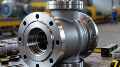
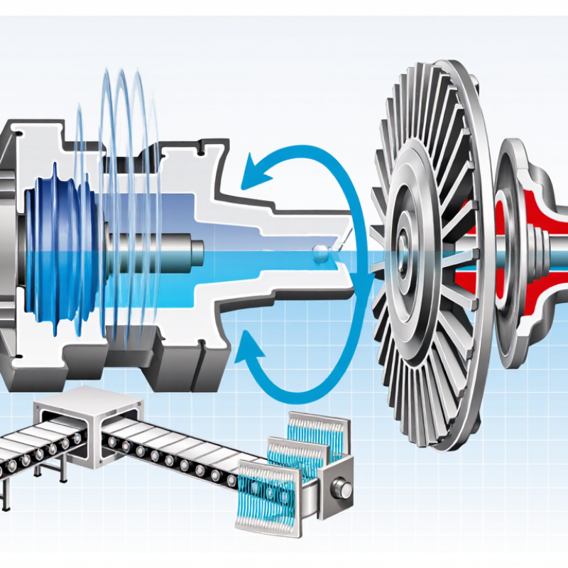
A fluid coupling is a hydrodynamic device that transfers rotary power between two shafts through moving fluid. The driving shaft turns an impeller, which accelerates the fluid inside a sealed housing. That flow pushes against a turbine, also called a runner, and makes the output shaft rotate. A small speed difference between the two sides is normal. It allows smooth starts, but also creates heat.
The main components are the impeller, turbine, housing, and working fluid, commonly oil. The impeller has curved blades that direct fluid outward. The turbine’s blades receive the flow and turn with it. Fluid then circulates back toward the impeller. The housing contains the fluid and helps protect internal parts. Seals limit leakage, while bearings support rotating shafts. Real flow is less tidy than this simple picture; blade shape, fluid condition, and load all affect performance.
Tips: Check for fluid leaks, unusual vibration, and excessive heat during maintenance. Follow the equipment maker’s fluid and service guidance. A coupling that feels warm may be operating normally, but a sudden temperature change deserves attention.
How Fluid Motion Transfers Torque Between Shafts
A fluid coupling transfers rotation through moving fluid rather than a solid connection between shafts. Inside its sealed housing, an input impeller spins and accelerates the oil. The moving fluid then strikes the blades of an output turbine, making the connected shaft rotate. The flow carries momentum across the gap. No gears are needed.
Torque transfer depends on the difference between input and output speeds. Some slip is necessary for the coupling to work, especially when a machine starts under load. That slip also creates heat. A fluid coupling can soften shock loads and allow gradual acceleration, but it does not multiply torque like a torque converter. Its behavior can feel less predictable when the fluid is hot or the load changes suddenly.
Tips: Watch for leaks, unusual heat, and changes in starting behavior. Check fluid condition and service intervals against the equipment specifications. Small warning signs matter.
For example, a conveyor may start smoothly as its motor turns the impeller and fluid gradually drives the output. If the belt is overloaded, the shafts may keep rotating at noticeably different speeds. Persistent slip can waste energy and raise operating temperatures. That is easy to overlook. Do not assume a coupling is failing from one warm reading alone; compare readings under similar loads and operating conditions.
The Coupling’s Operating Sequence from Startup to Steady Speed
A fluid coupling transfers power through moving oil rather than a rigid connection. At startup, the motor turns the input impeller, which circulates oil inside the housing. The oil strikes the output runner and begins turning the connected machine. The runner usually lags behind the impeller at first. That speed difference, called slip, allows torque to pass through the fluid.
As the load accelerates, the output shaft gains speed and slip decreases. The coupling does not lock completely; a small speed difference remains during normal operation. Under heavier loads, slip and heat can rise. A warm housing is expected, but a sudden temperature increase may point to overload, poor ventilation, or an oil problem. One detail is easy to underestimate: acceleration time depends on both the driven load and the coupling’s condition. Real installations can behave less smoothly than a diagram suggests.
Tips: Check the specified oil level before startup, and keep air passages clear. Listen for unusual vibration, then compare operating temperature with the equipment’s normal readings. Do not judge performance from shaft speed alone; note the load and startup time too.
Common Fluid Coupling Designs and Their Differences
A fluid coupling transfers rotation through oil rather than direct mechanical contact. Inside its housing, an impeller throws fluid toward a turbine, turning the driven shaft. Some slip remains between the two halves. That slip creates heat, so oil condition and cooling matter.
Common designs differ mainly in how much fluid they hold and how that amount changes. A constant-fill coupling keeps a set fluid volume. It suits steady loads and softens starts, but offers limited control once running. A variable-fill design uses a scoop tube to adjust fluid volume while operating. This allows smoother control of driven speed and torque, though it adds control hardware and maintenance points. A delay-chamber design initially holds some fluid away from the working circuit. The gradual fill can reduce starting torque for high-inertia equipment, such as a loaded conveyor. Details vary by design.
The U.S. Department of Energy’s 2014 motor-systems sourcebook estimates that motor-driven systems use about 68% of U.S. manufacturing electricity. That figure is not a fluid-coupling efficiency rating; it shows why matching the drive to the load deserves care. Constant-fill units are simpler, while variable-fill units offer more adjustment. Neither removes slip losses. I would check the load profile, starts per hour, and cooling needs before choosing—catalog comparisons alone can miss real operating conditions.
What Is a Fluid Coupling and How Does It Work?
A fluid coupling transfers torque through moving fluid between an input impeller and an output runner. The chart shows how slip relates to speed ratio; the plotted points are illustrative values calculated using the definition shown below, not product test data.
Slip (%) = (input speed − output speed) ÷ input speed × 100. For example, a speed ratio of 0.90 means the output runs at 90% of input speed, giving 10% slip.
Common Fluid Coupling Designs
- Constant-fill: Uses a fixed amount of working fluid. It is a straightforward design, and output speed depends on load and slip.
- Variable-fill: Changes the amount of fluid in the working circuit, often with a scoop tube, to regulate transmitted torque and output speed.
- Delayed-fill: Uses a reservoir or delay chamber to fill the working circuit gradually, helping limit starting torque and smooth acceleration.
Typical Applications and Key Performance Factors
Fluid couplings appear in conveyors, crushers, mixers, and large pumps, where motors must start heavy loads without a harsh mechanical shock. The impeller spins in oil, moving fluid against a runner connected to the driven shaft. That is the basic action. The gradual torque transfer helps reduce starting stress on belts, gears, and shafts. It can also soften brief load changes, though it cannot remove every shock.
Selection depends on starting torque, load inertia, operating speed, and heat capacity. Too much slip turns useful power into heat. Heat matters. For pump and fan duties, the coupling’s speed difference under load affects both control and energy use. The U.S. Department of Energy’s 2014 report, Improving Motor and Drive System Performance, estimates motor-driven systems use about 69% of U.S. industrial electricity. That figure covers motor systems broadly, not fluid couplings alone, but it shows why matching drive components deserves care. Check oil condition, cooling airflow, alignment, and the expected start frequency; a coupling that performs well on paper may still run hot in a cramped enclosure.

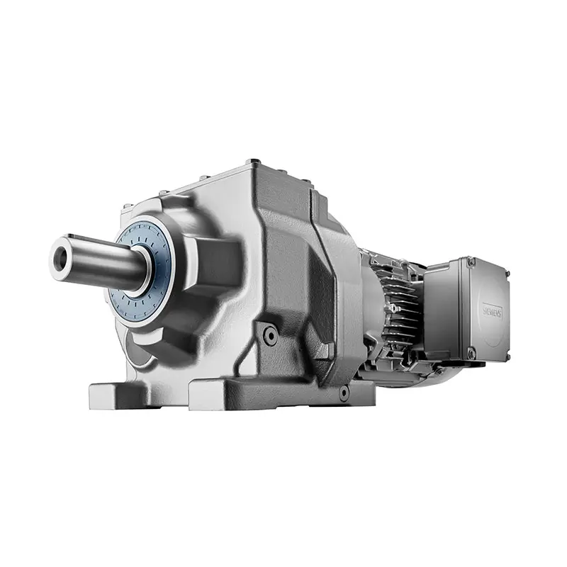 SIEMENS Helical Gearmotor Low Voltage
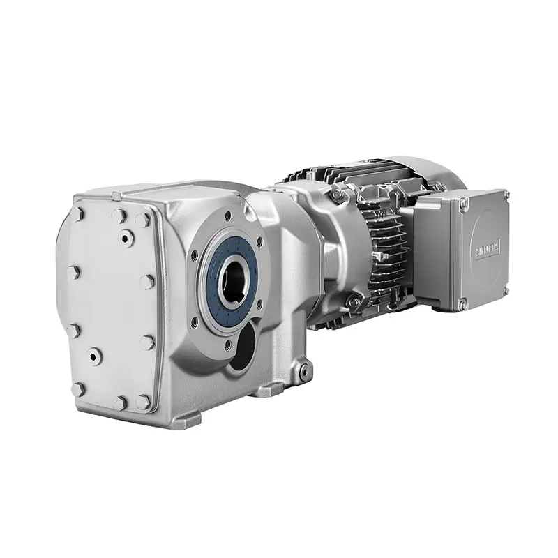 SIEMENS Bevel Helical Gearmotor
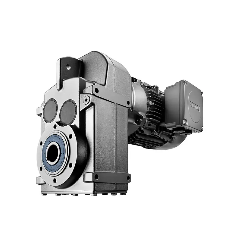 SIEMENS Parallel Shaft Gearmotor
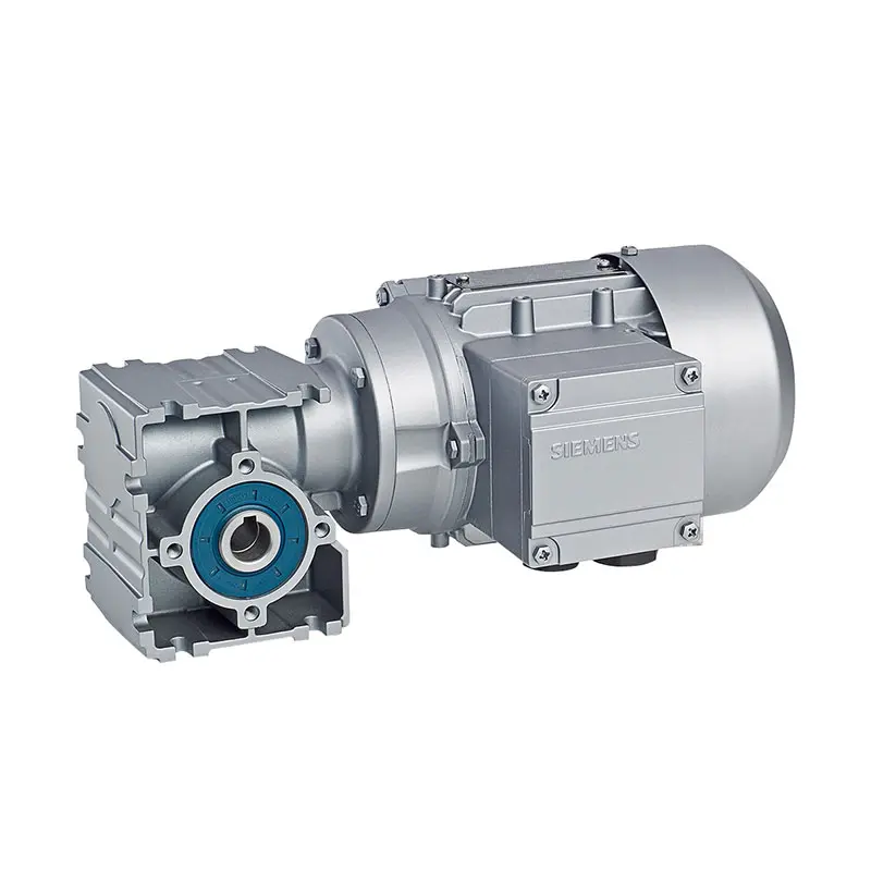 SIEMENS Worm Gearmotor Low Voltage
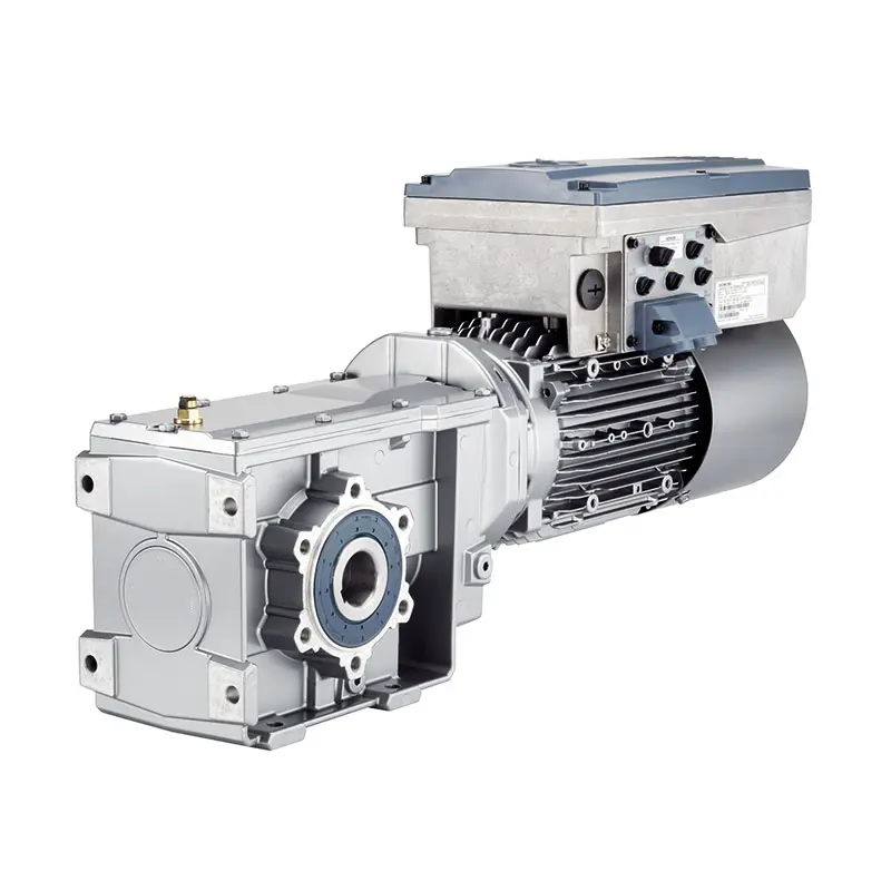 SIEMENS With Servo Motor Gearmotor
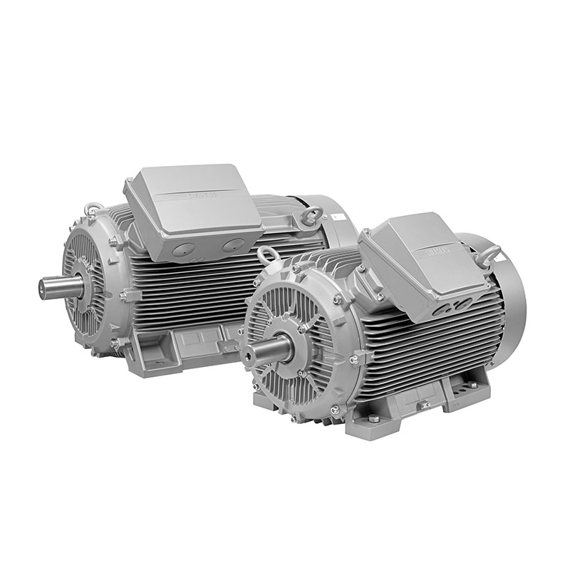 SIEMENS Low Voltage Motor Low Voltage
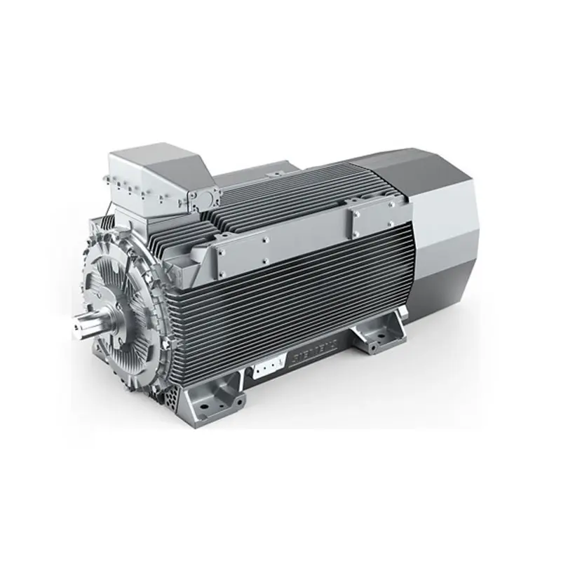 SIEMENS High Voltage Motor Low Voltage
 SIEMENS Marine Motor Low Voltage
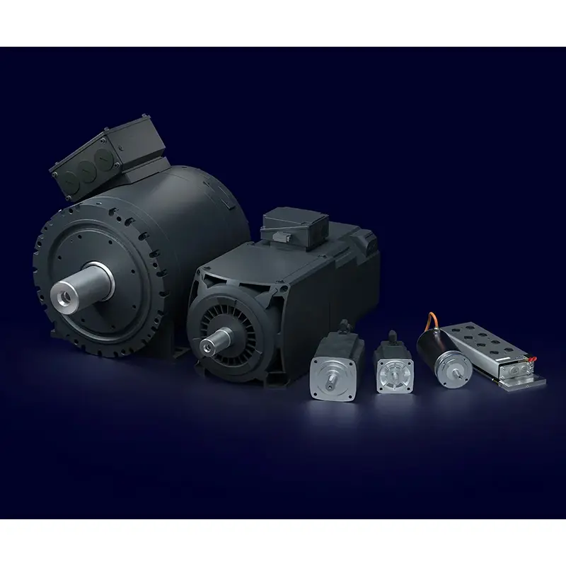 SIEMENS Servo Motor Low Voltage
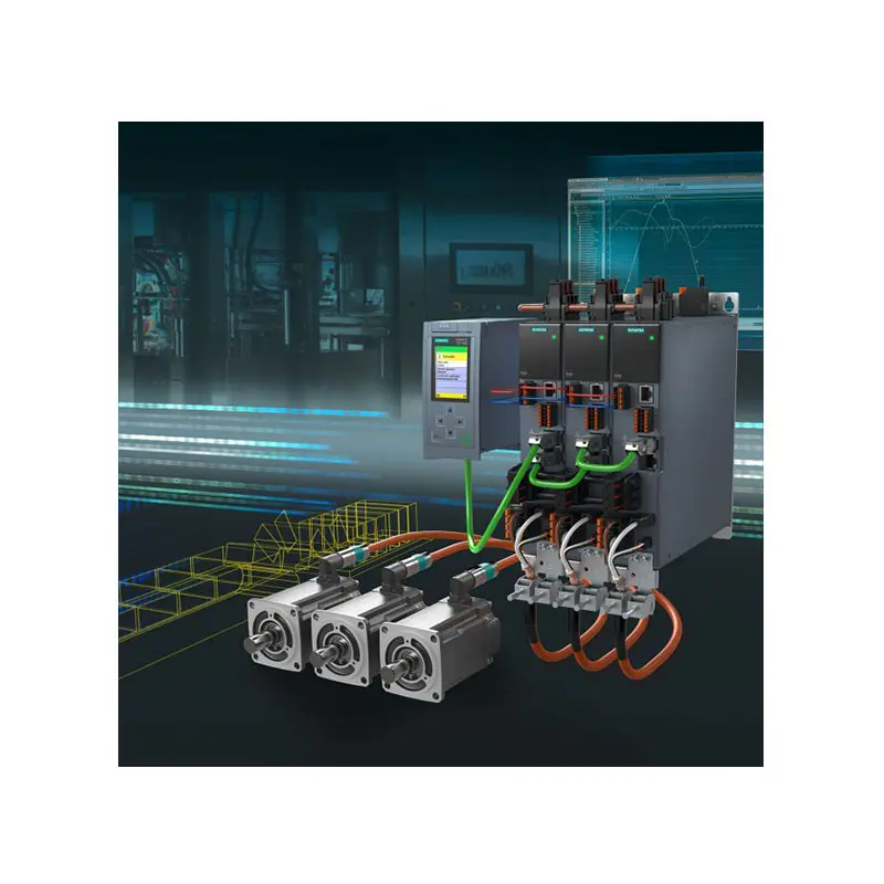 SIEMENS SINAMICS S210 Low Voltage
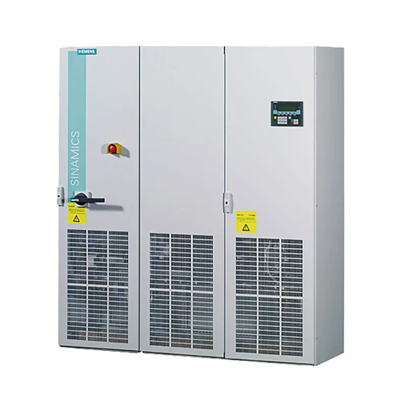 SIEMENS SINAMICS S150 Low Voltage
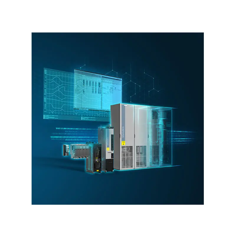 SIEMENS SINAMICS S120 Low Voltage
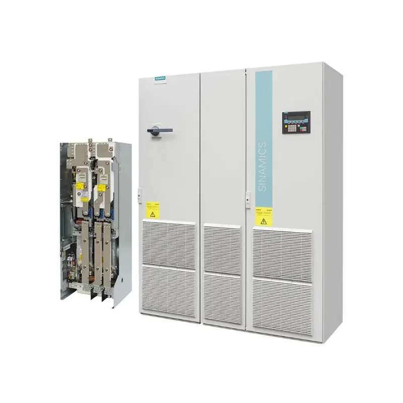 SIEMENS SINAMICS G130/G150
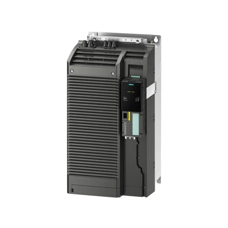 SIEMENS SINAMICS G120 Low Voltage
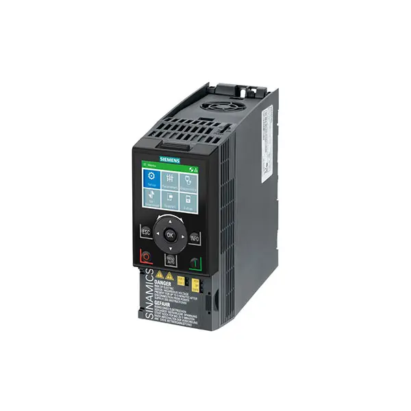 SIEMENS SINAMICS G120C Low Voltage
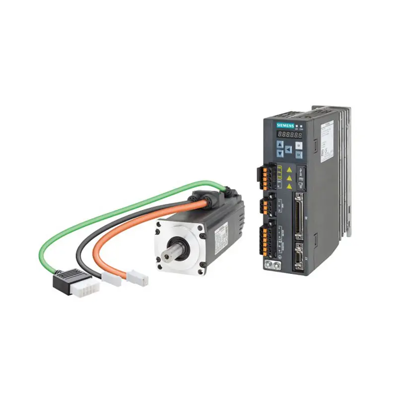 SIEMENS SINAMICS V90
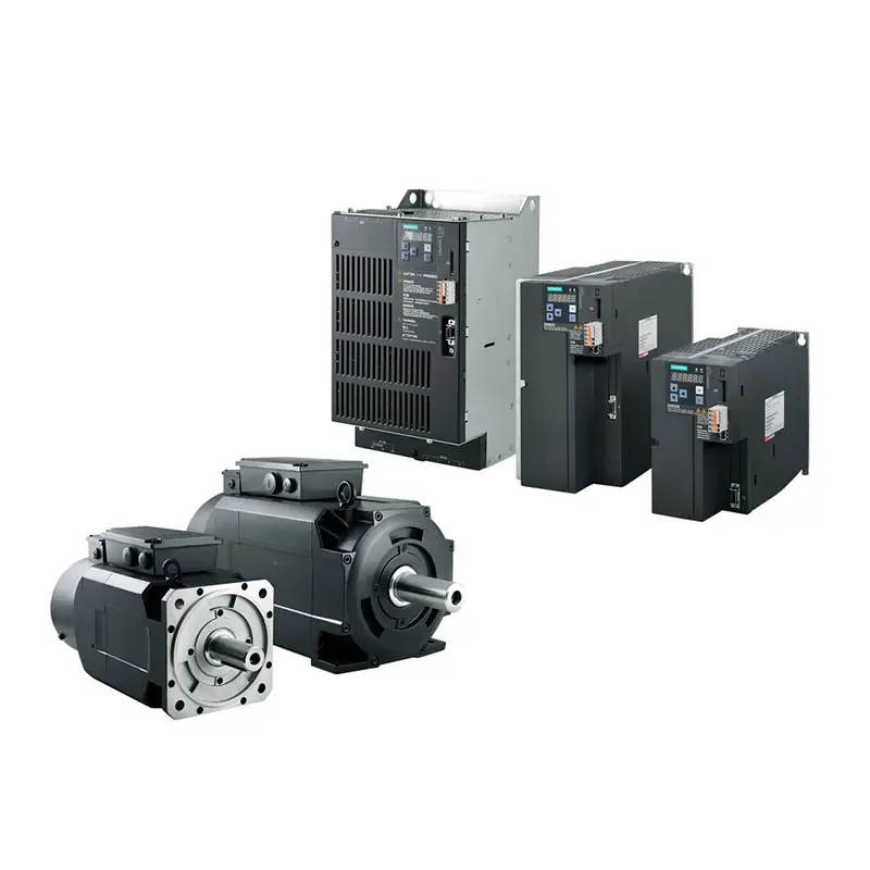 SIEMENS SINAMICS V70 Low Voltage
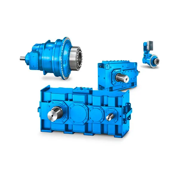 FLENDER Gear Unit
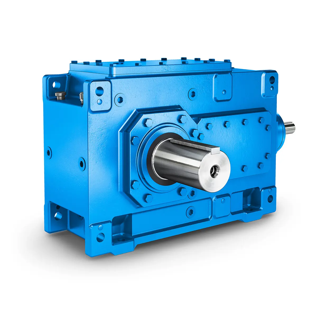 FLENDER Helical Gear Unit
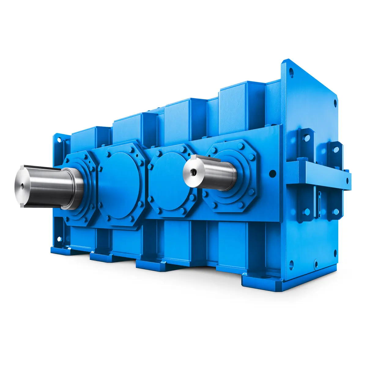 Flender gear units for lifting and luffing gears
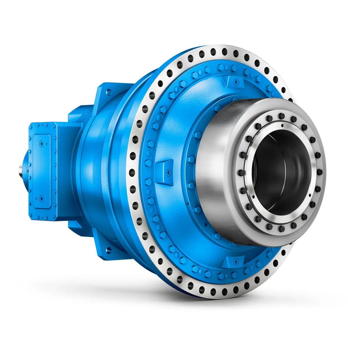 FLENDER Gear Unit gearunit gearbox
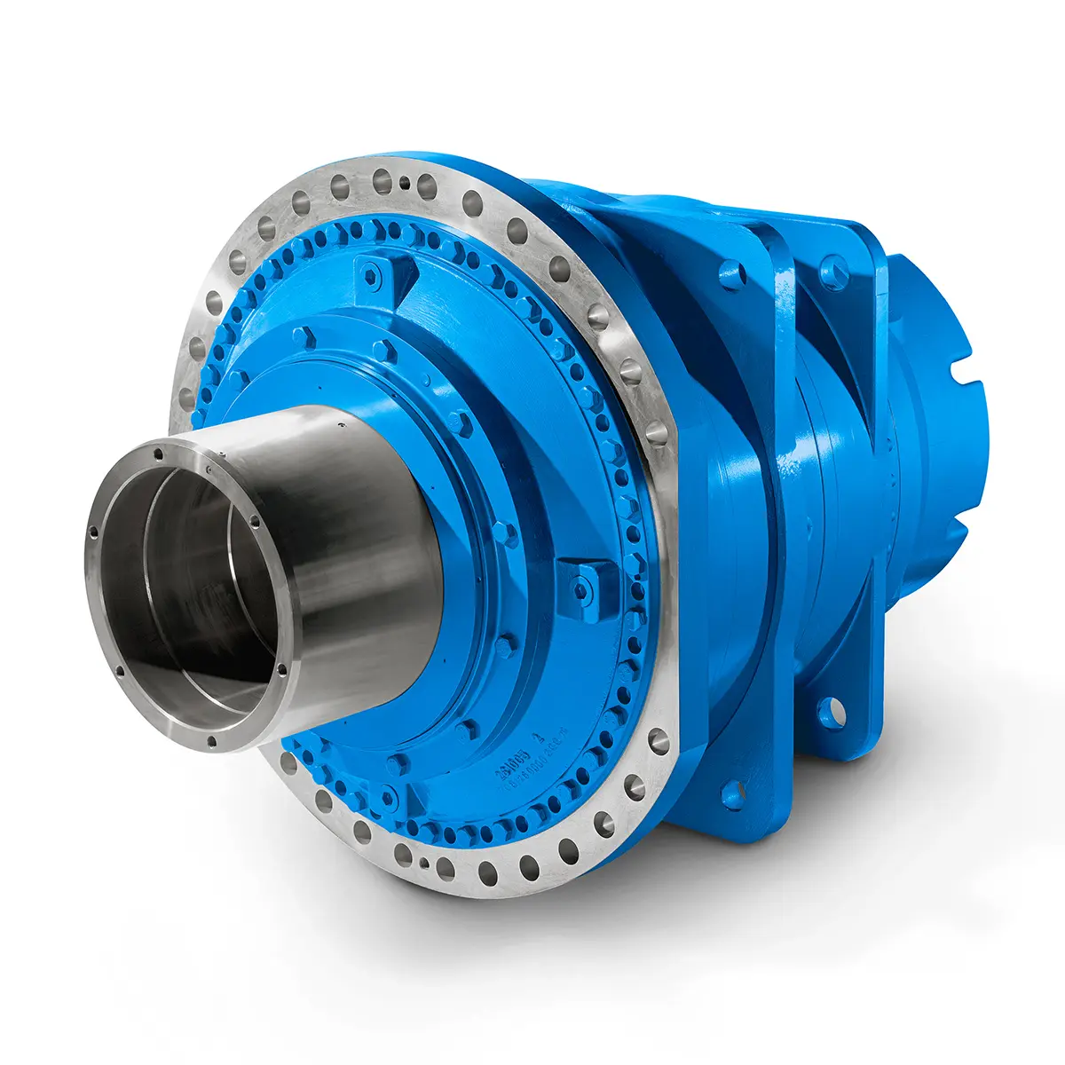 Optimal Drive Solution For Maximum Performance
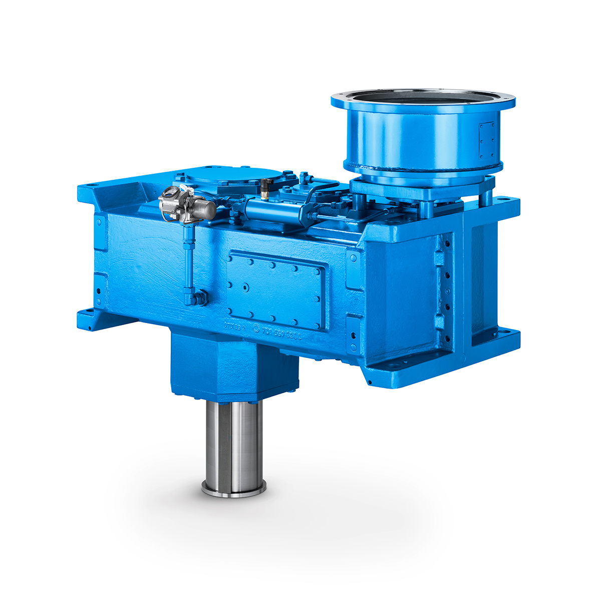 Strongly operating against biodegradable constituents
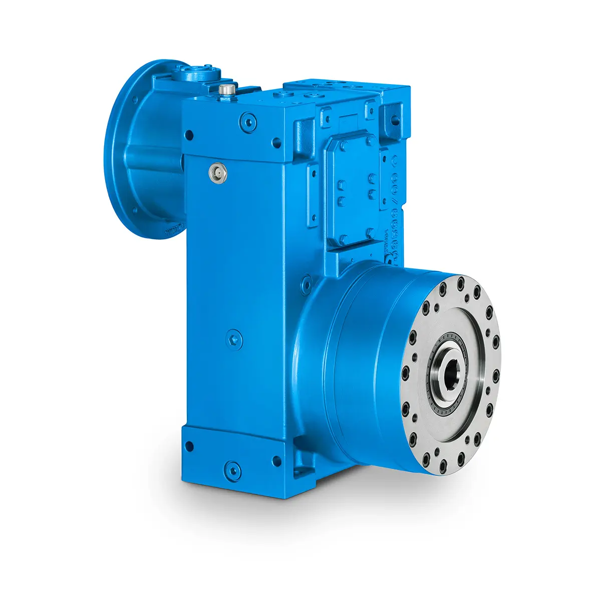 SINGLE SCREW Special industry dedicated gearunit gearbox
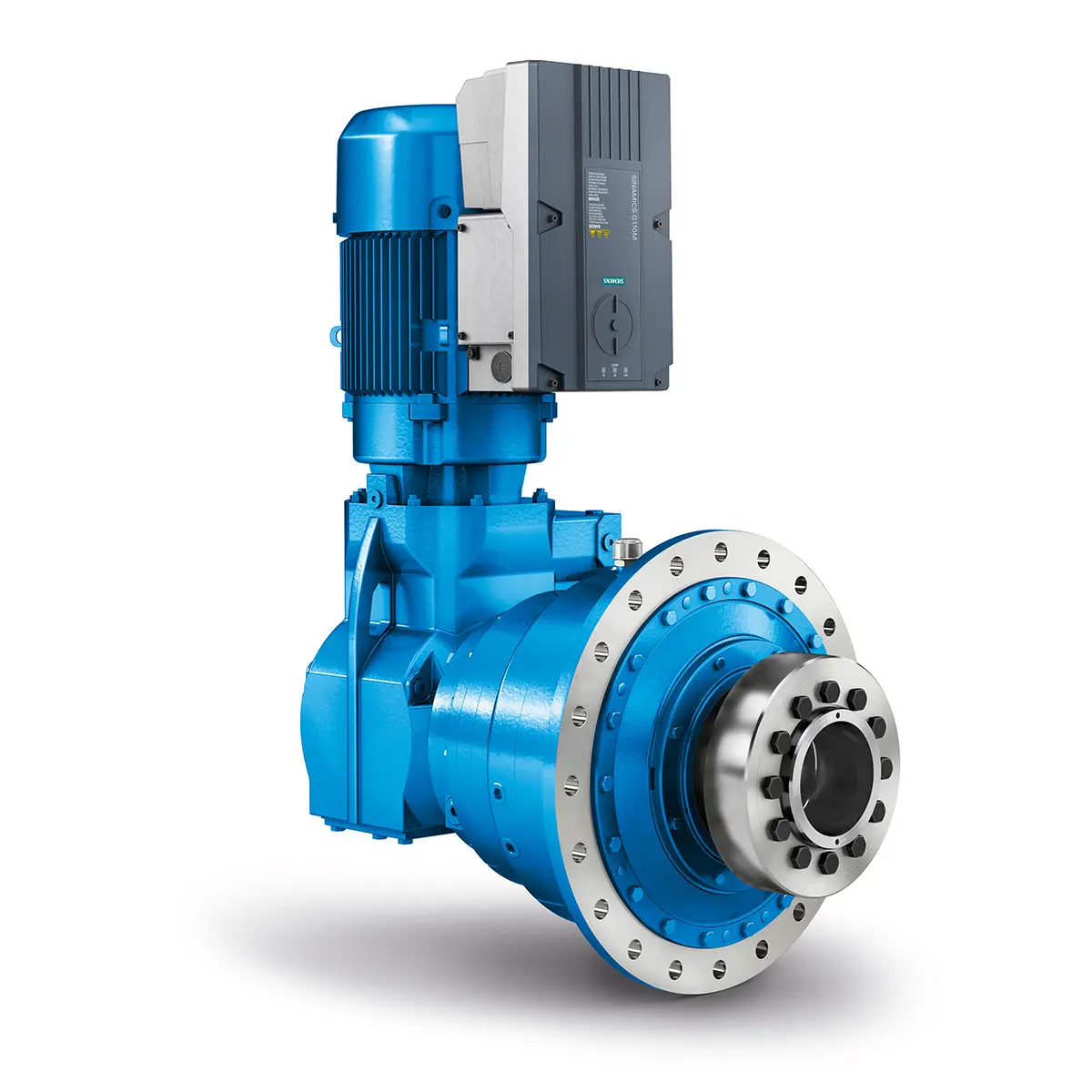 Playmaker In The Premium League
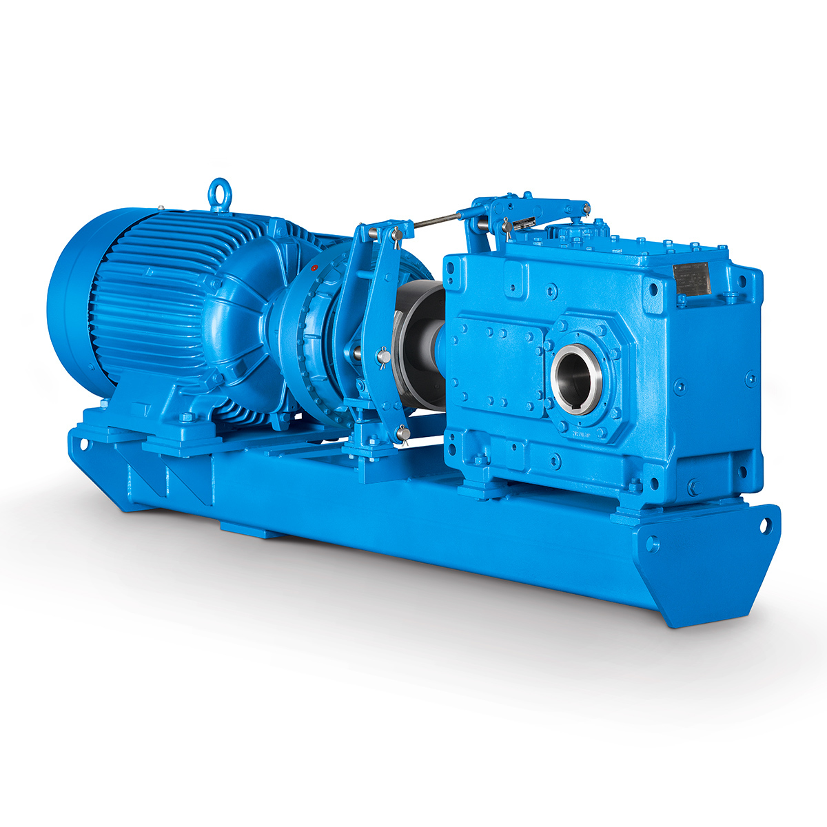 Conveyor belts gearunit gearbox
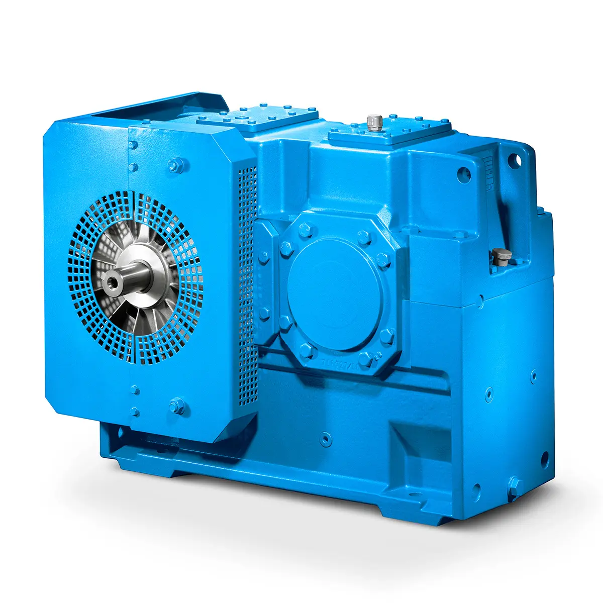 Paper And Pulp Preparation Sections
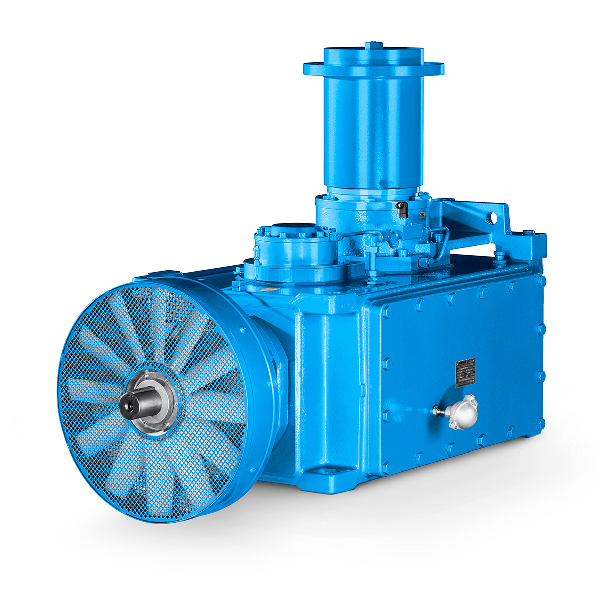 Operational Reliability Even In Case Of The Highest Ventilation Forces
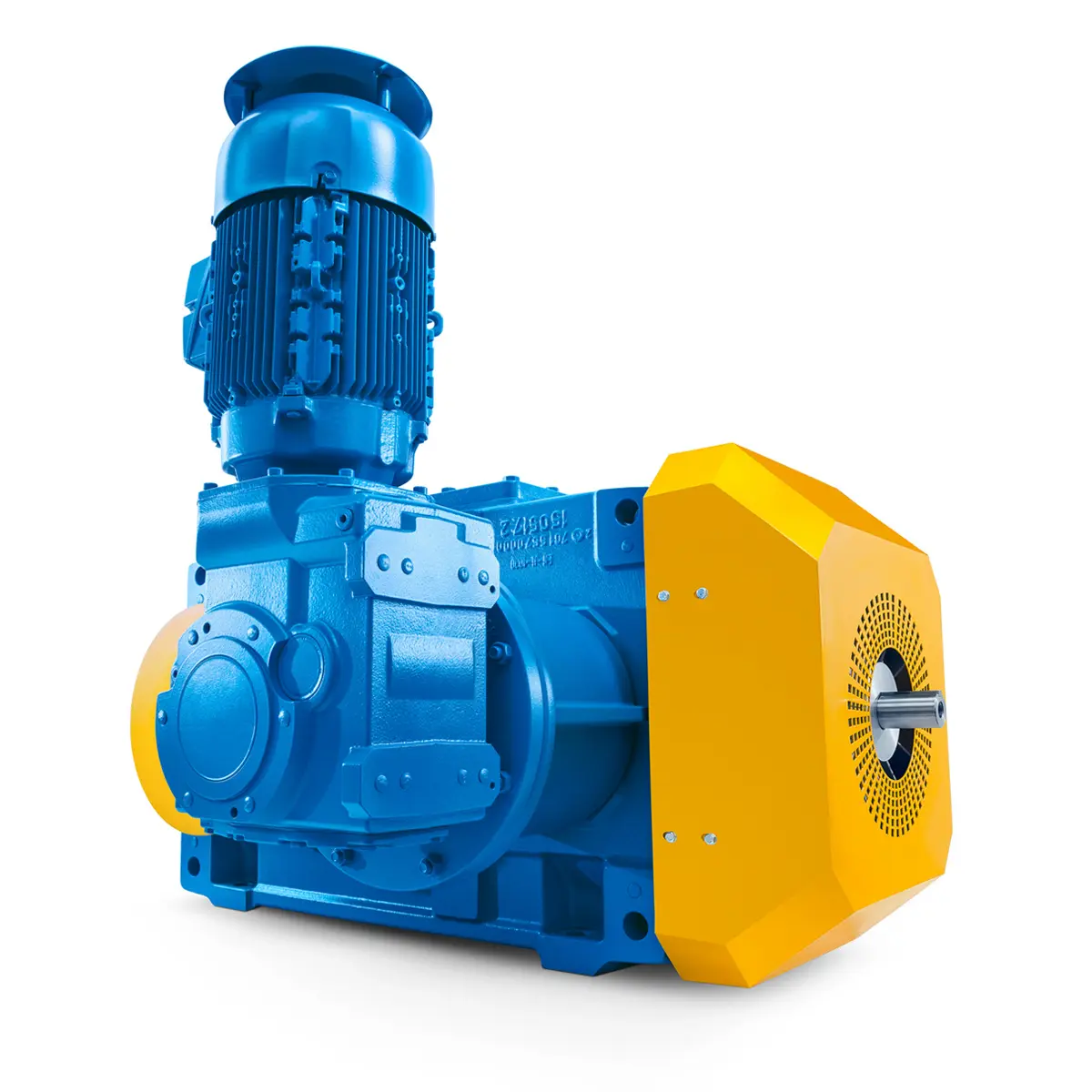 Reliable Gear Units For High Performance Vertical Conveyors 59/200
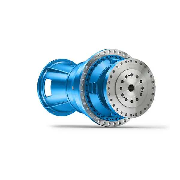 Maximum power density – PLANUREX 3 L individual drives for your sugar cane mill
 The proven all rounder gearunit gearbox
 Stirs and stirs and stirs gearunit gearbox
 Flexibility on Board gearunit gearbox
 The right gearbox for all Multi-Engine Ships
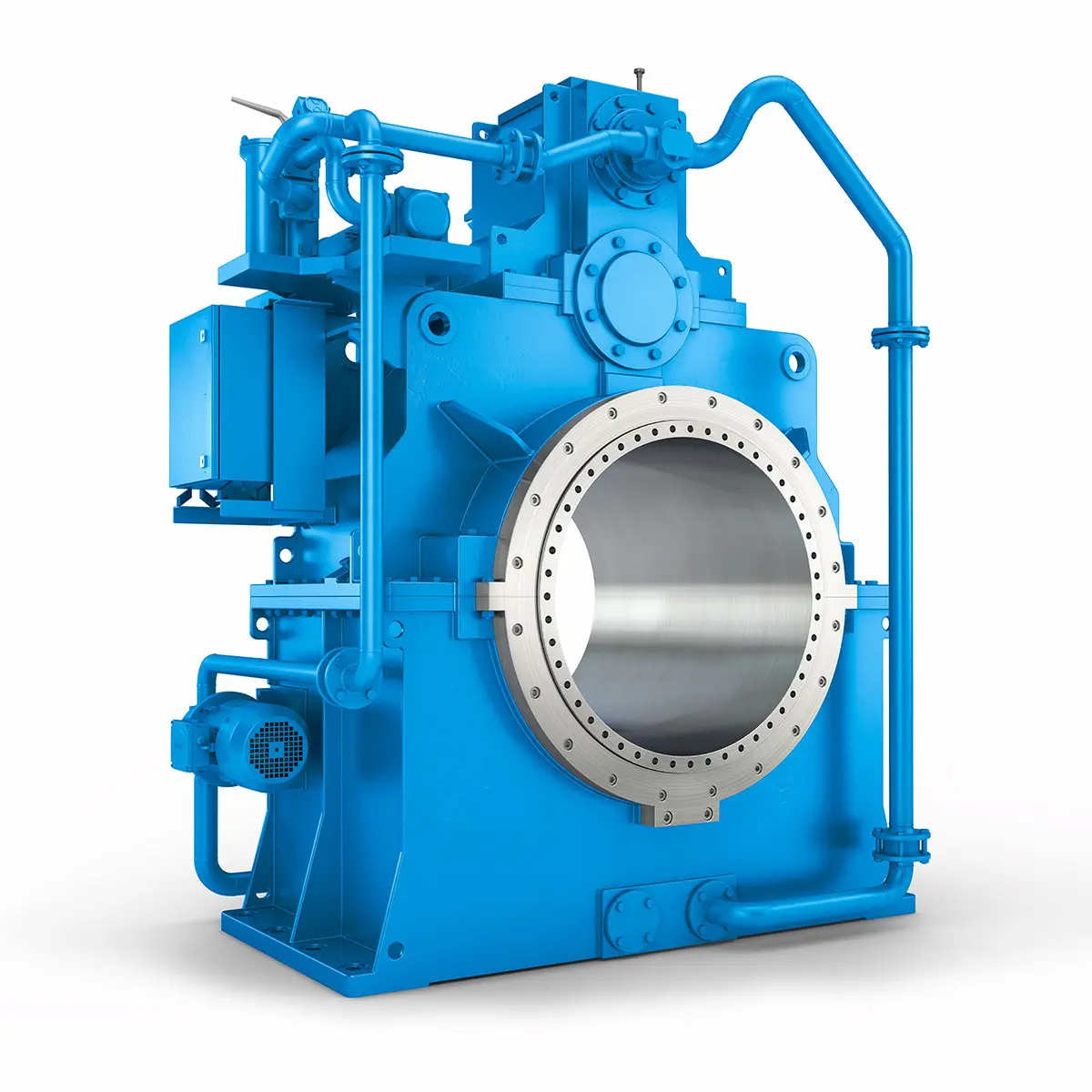 Reliable Power Generation on board
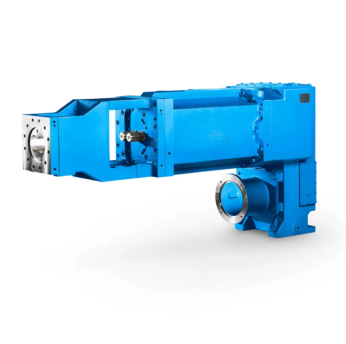 Maximum performance level, fast deliverable
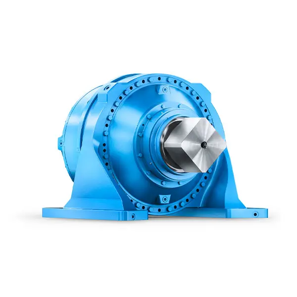 Efficient and compact – FLENDER Gear Units for Sugar Mills
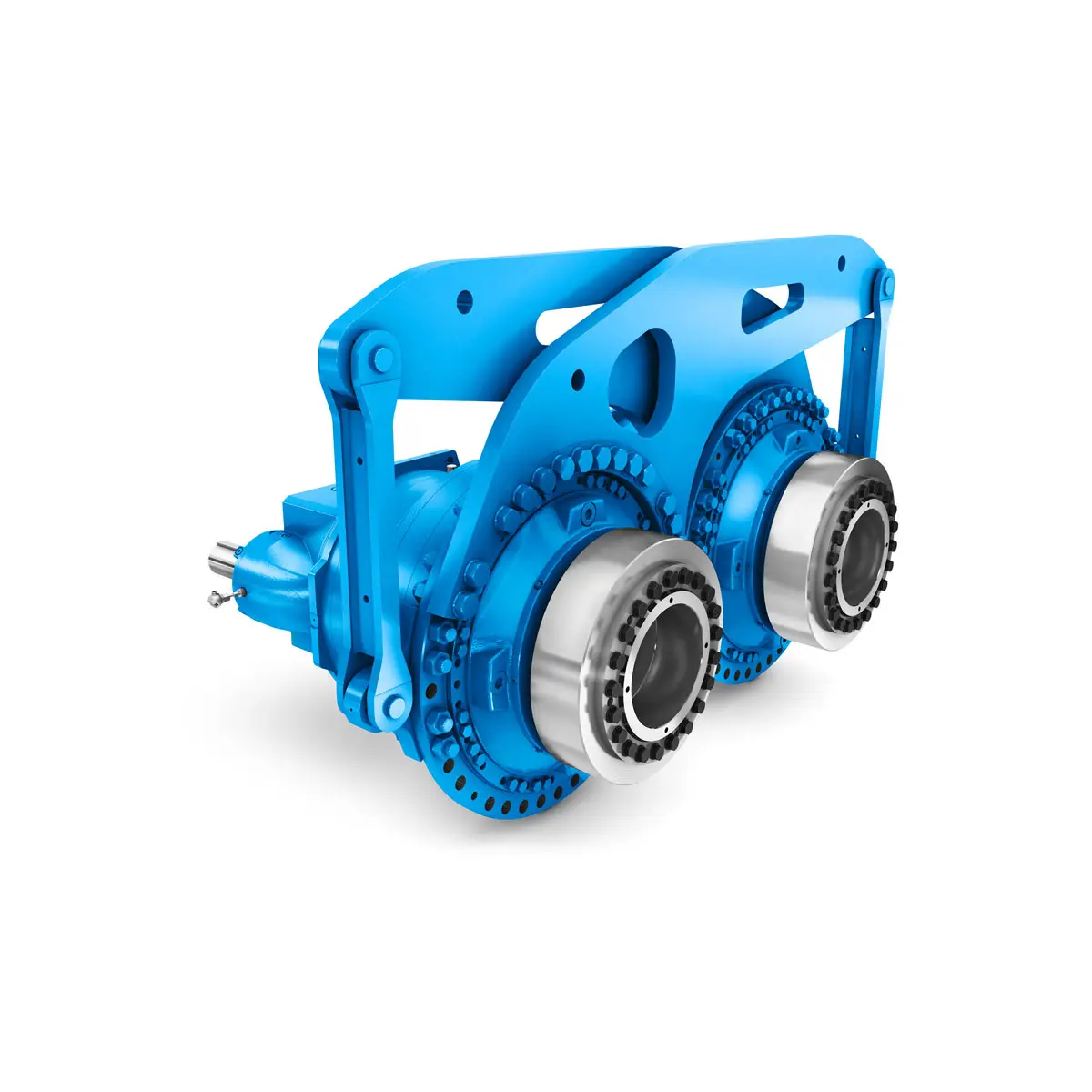 Extremely strong. Extremely compact. Extremely stressable.
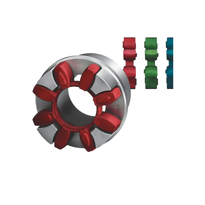 FLENDER Coupling
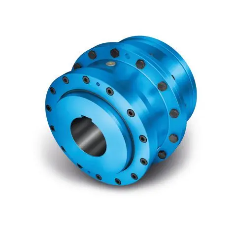 ZAPEX ZW Torsionally Rigid Gear Coupling
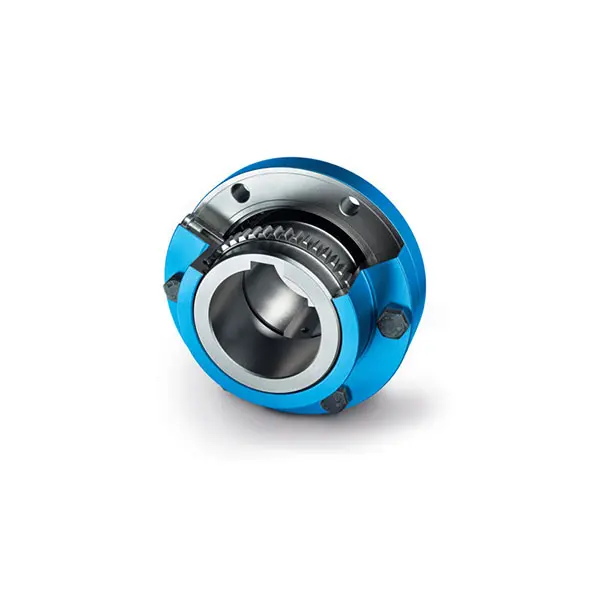 ZAPEX ZN Torsionally Rigid Gear Coupling
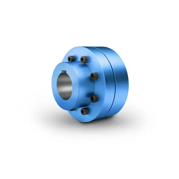 N-EUPEX Flexible high performance Coupling
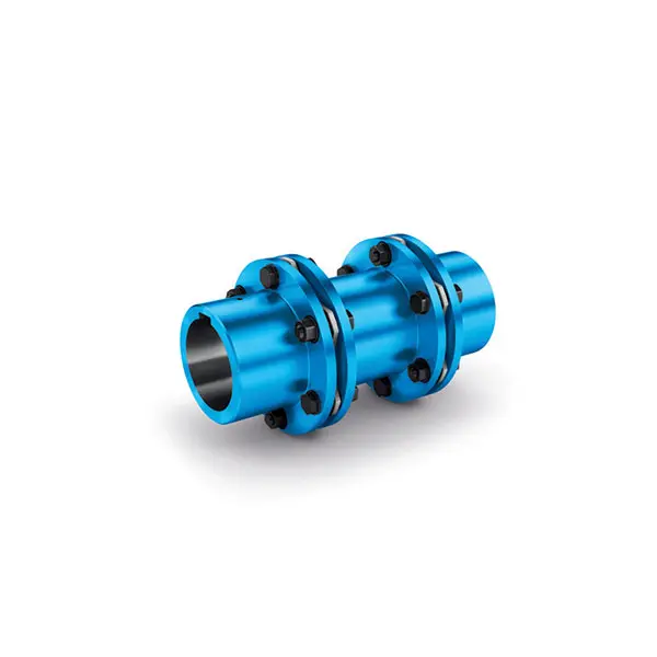 N-ARPEX Torsionally Rigid All-Steel Coupling
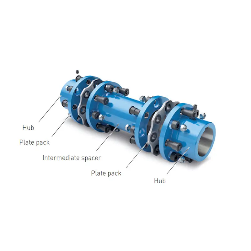 ARPEX Torsionally Rigid All-Steel Coupling Spare and Parts
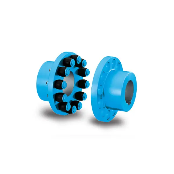 RUPEX Flexible high performance Coupling
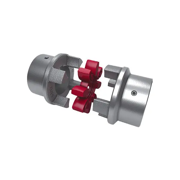 N BIPEX Flexible high performance coupling
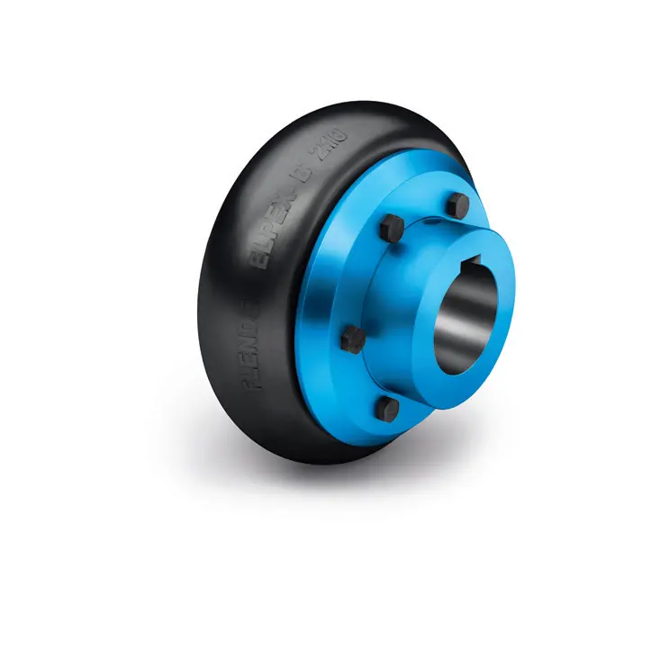 ELPEX B Highly Flexible Coupling
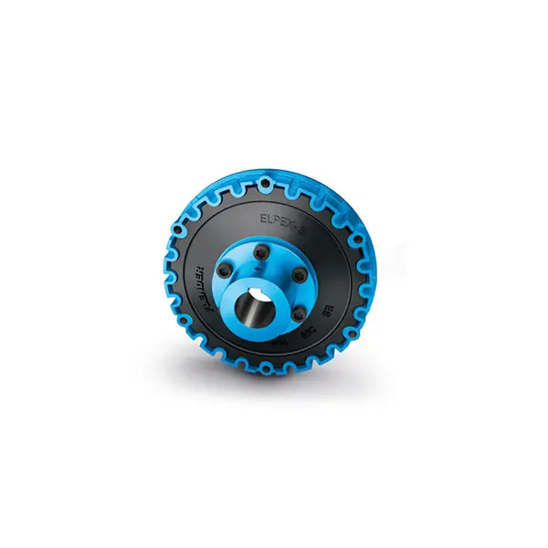 ELPEX S Highly Flexible Coupling high performance
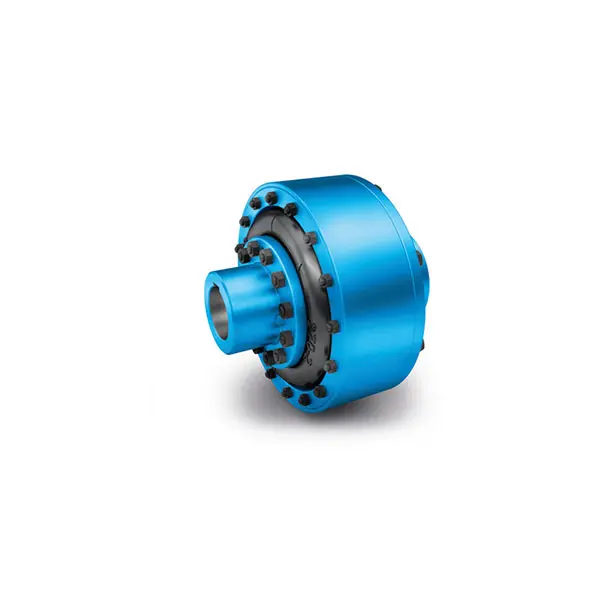 ELPEX Highly Flexible Coupling high performance
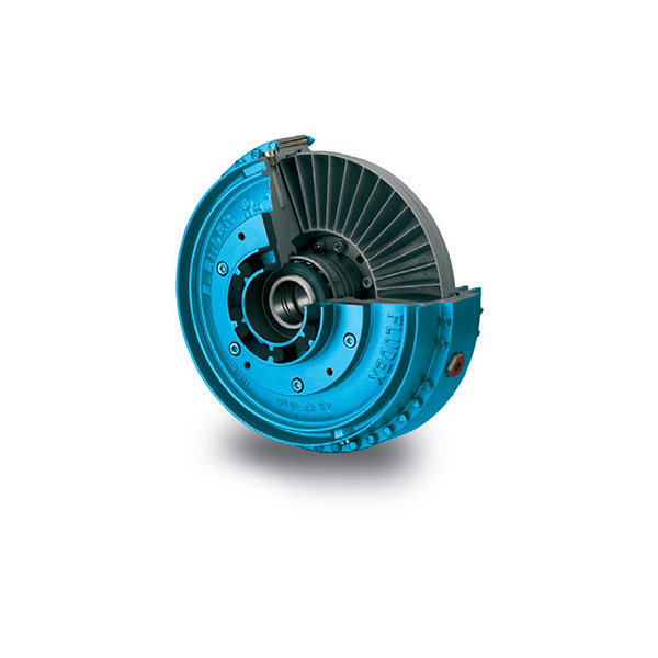 FLUDEX Fluid Coupling high performance
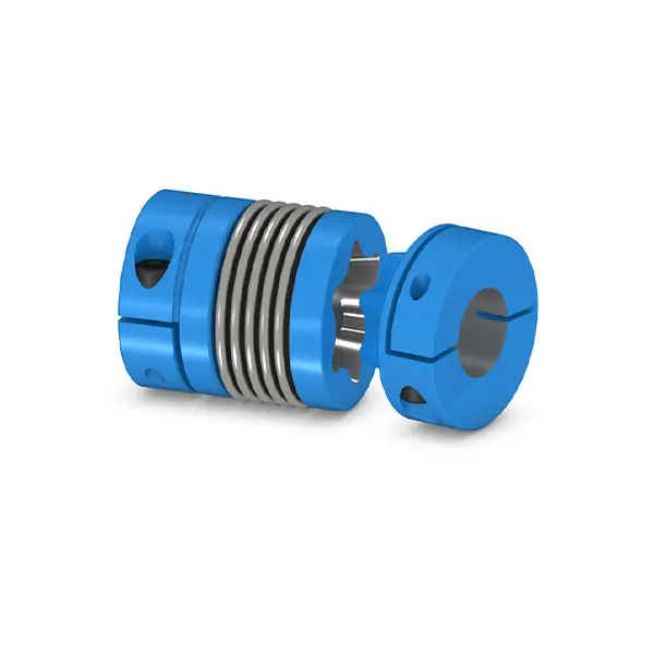 SIPEX Backlash free Coupling high performance
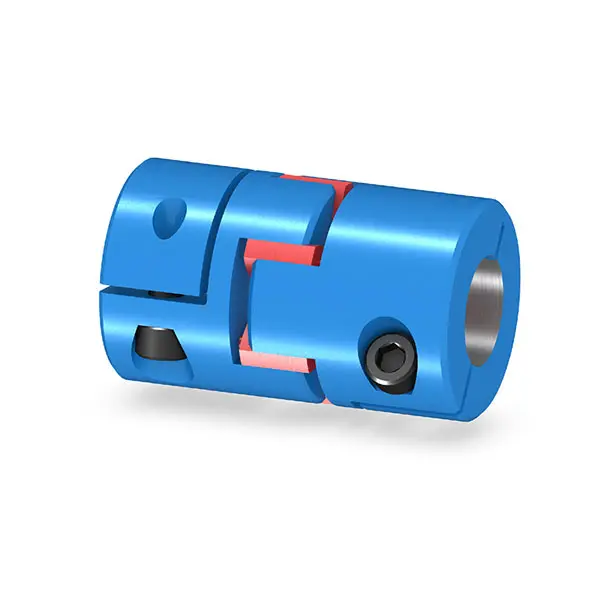 BIPEX S Backlash free Coupling high performance
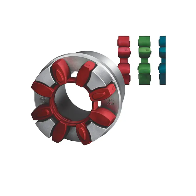 FLENDER Coupling Spare Parts high performance
 SEW Gearmotor
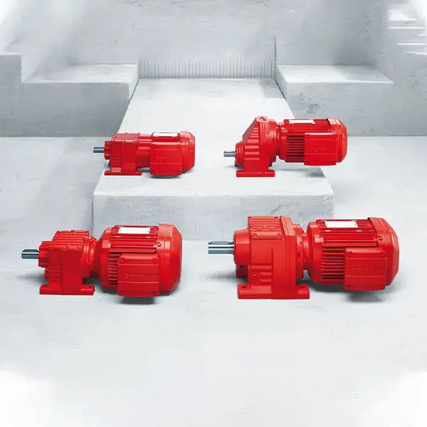 R Series Helical Gearmotor low voltage
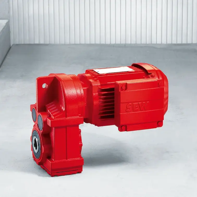 F Series Parallel Shaft Gearmotor low voltage
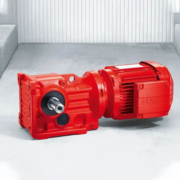 K Series Helical Bevel Gearmotor low voltage
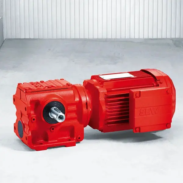 S Series Helical Worm Gearmotor low voltage
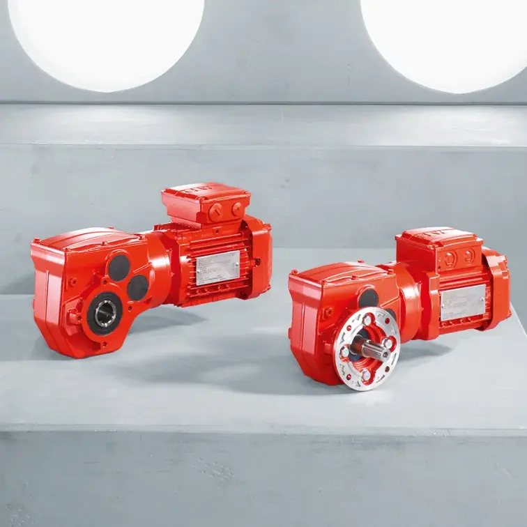 W Series SPIROPLAN® Right Angle Gearmotor