
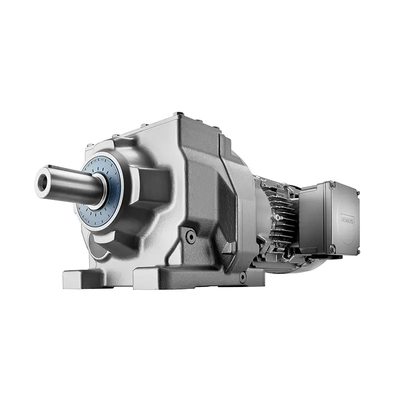
 SIEMENS Helical Gearmotor Low Voltage
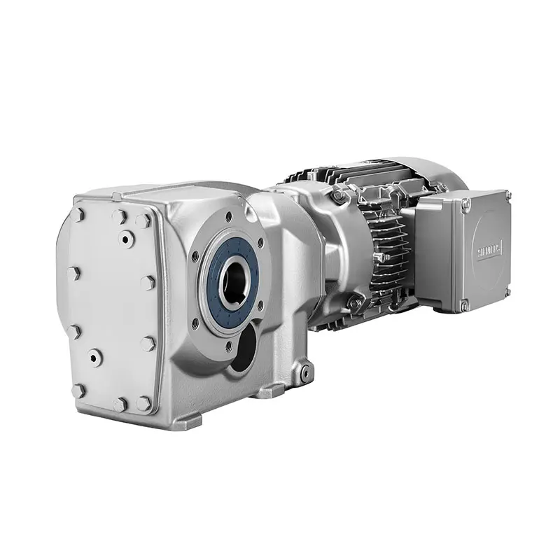 SIEMENS Bevel Helical Gearmotor
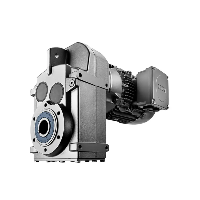 SIEMENS Parallel Shaft Gearmotor
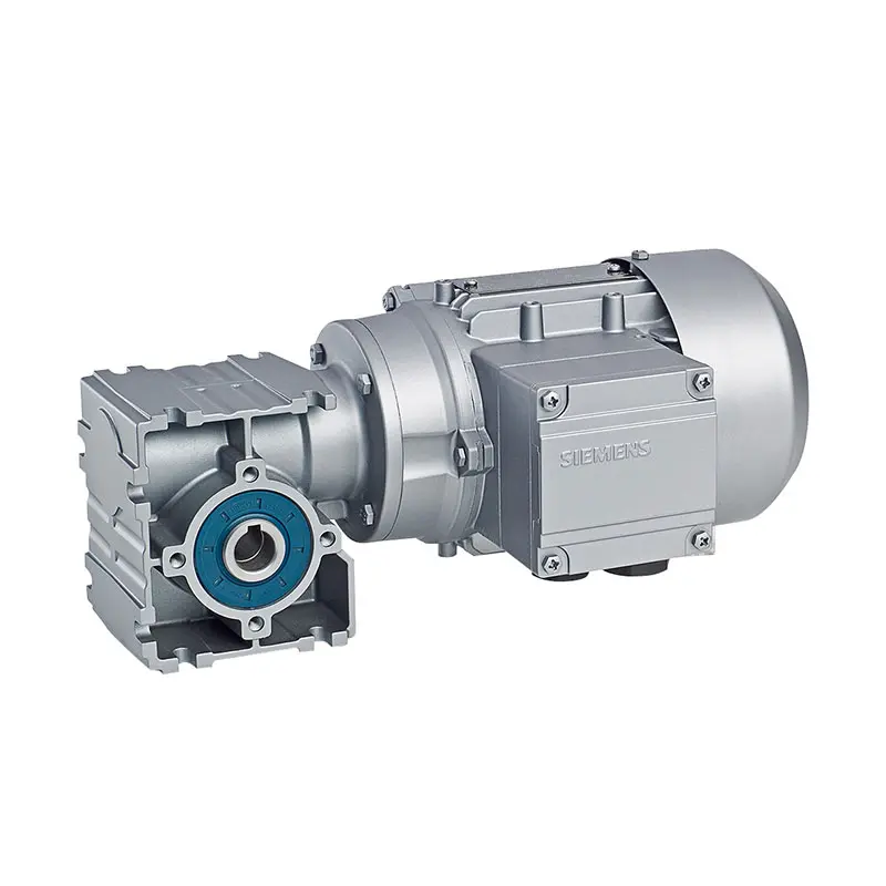 SIEMENS Worm Gearmotor Low Voltage
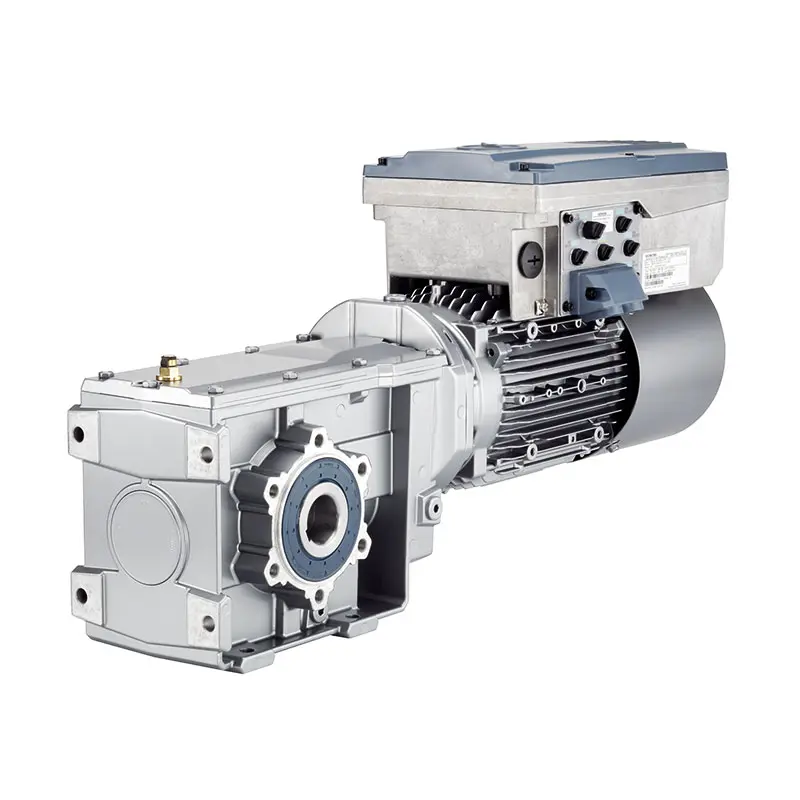 SIEMENS With Servo Motor Gearmotor
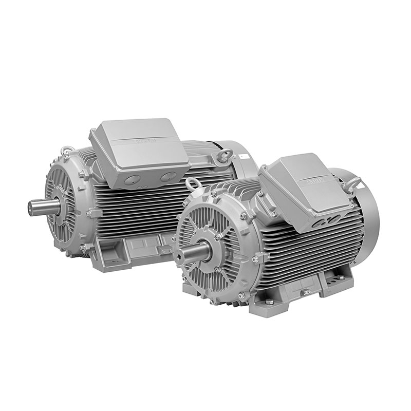 SIEMENS Low Voltage Motor Low Voltage
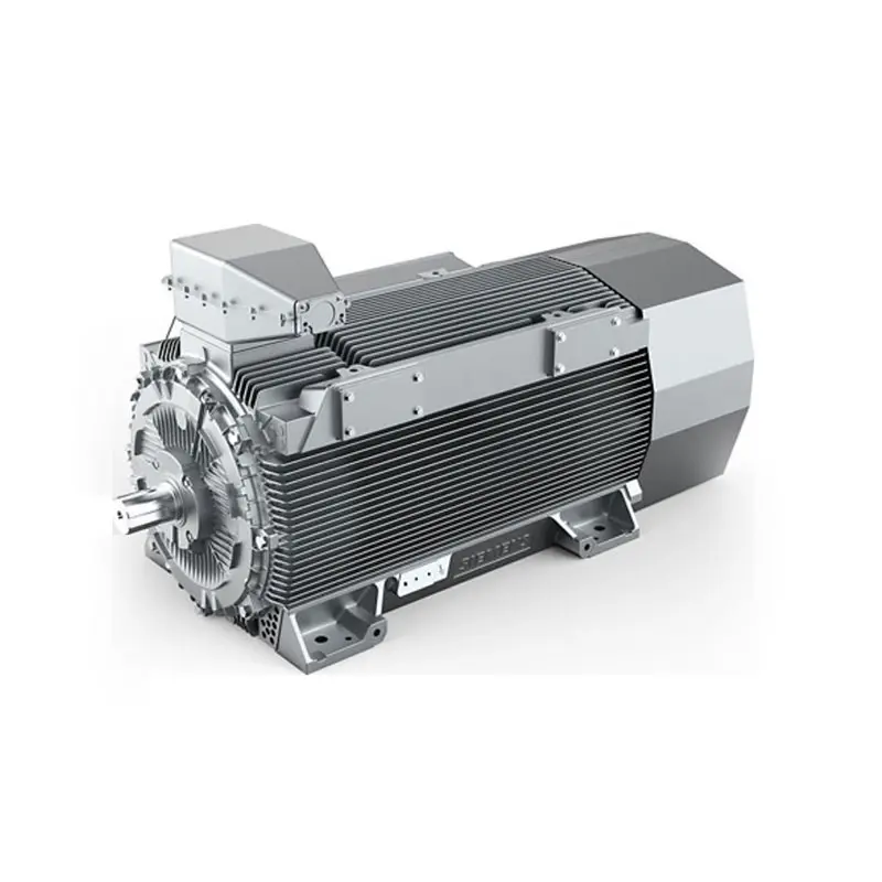 SIEMENS High Voltage Motor Low Voltage
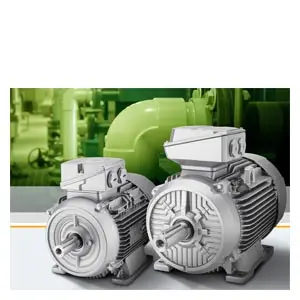 SIEMENS Marine Motor Low Voltage
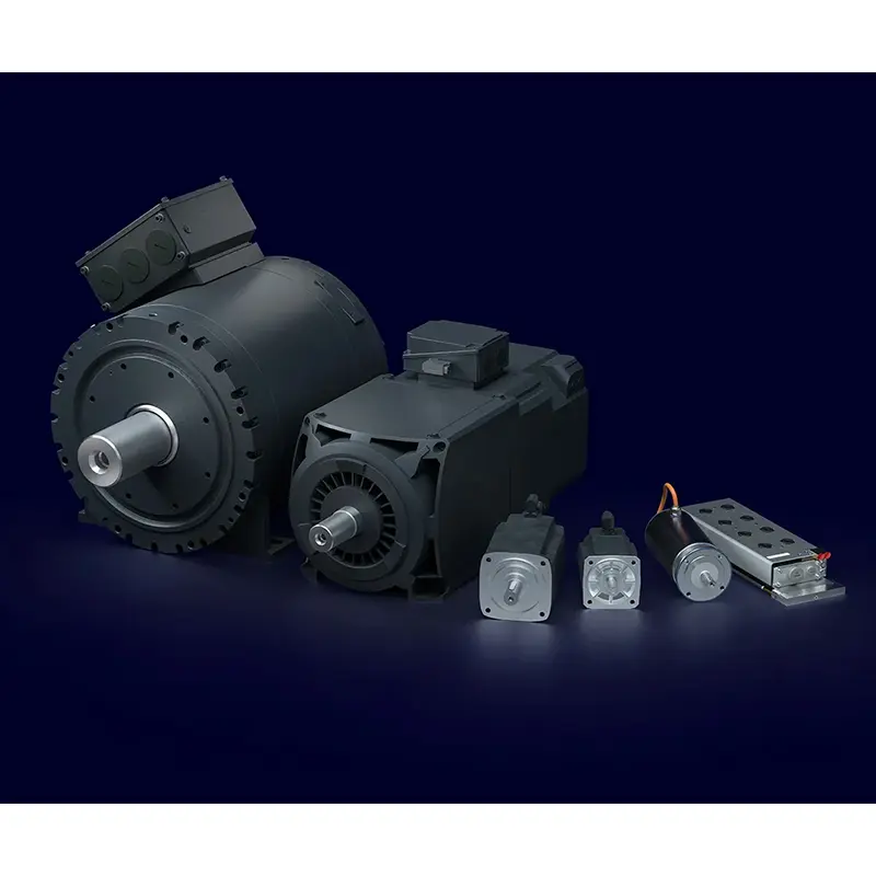 SIEMENS Servo Motor Low Voltage
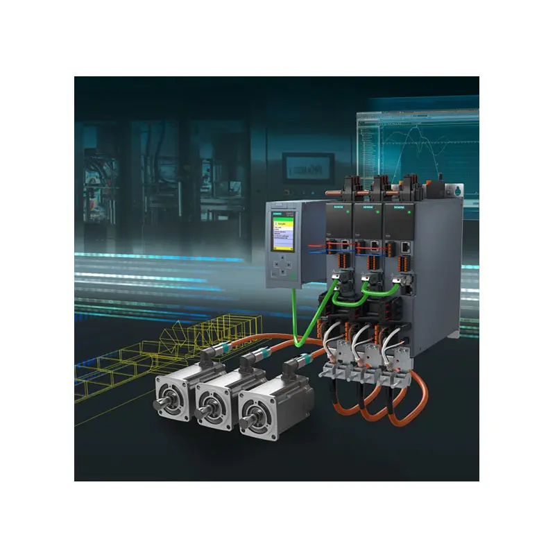 SIEMENS SINAMICS S210 Low Voltage
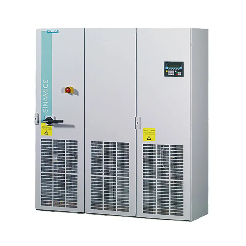 SIEMENS SINAMICS S150 Low Voltage
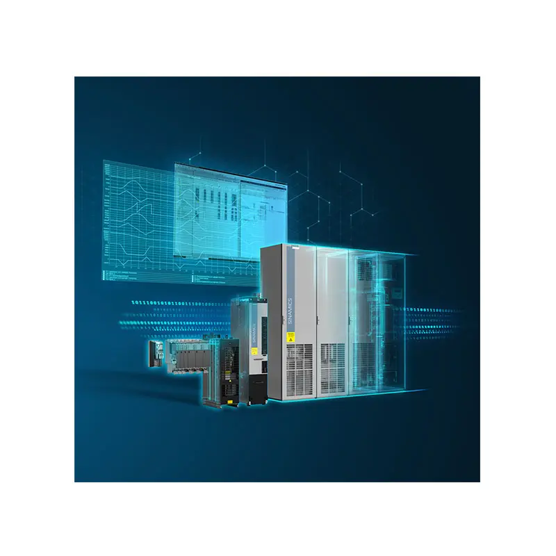 SIEMENS SINAMICS S120 Low Voltage
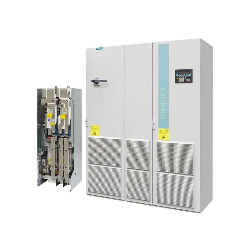 SIEMENS SINAMICS G130/G150
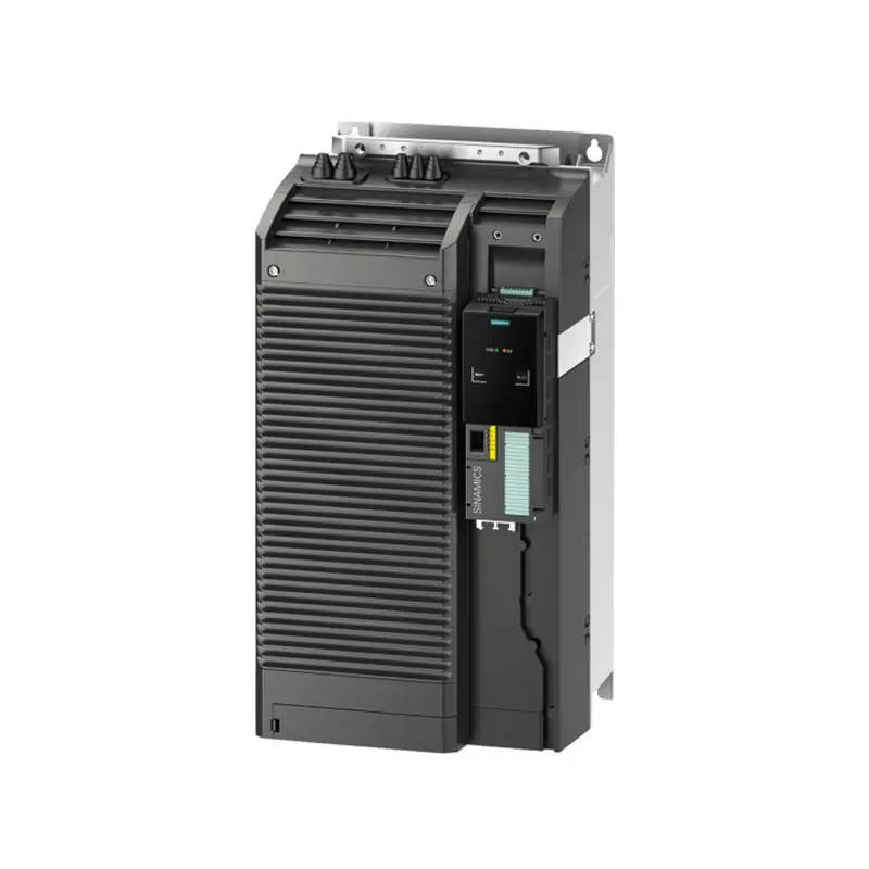 SIEMENS SINAMICS G120 Low Voltage
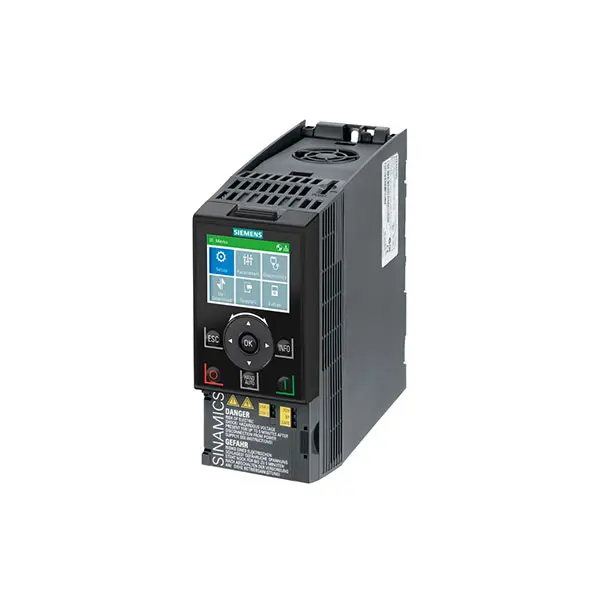 SIEMENS SINAMICS G120C Low Voltage
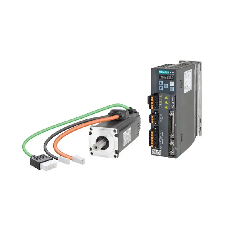 SIEMENS SINAMICS V90
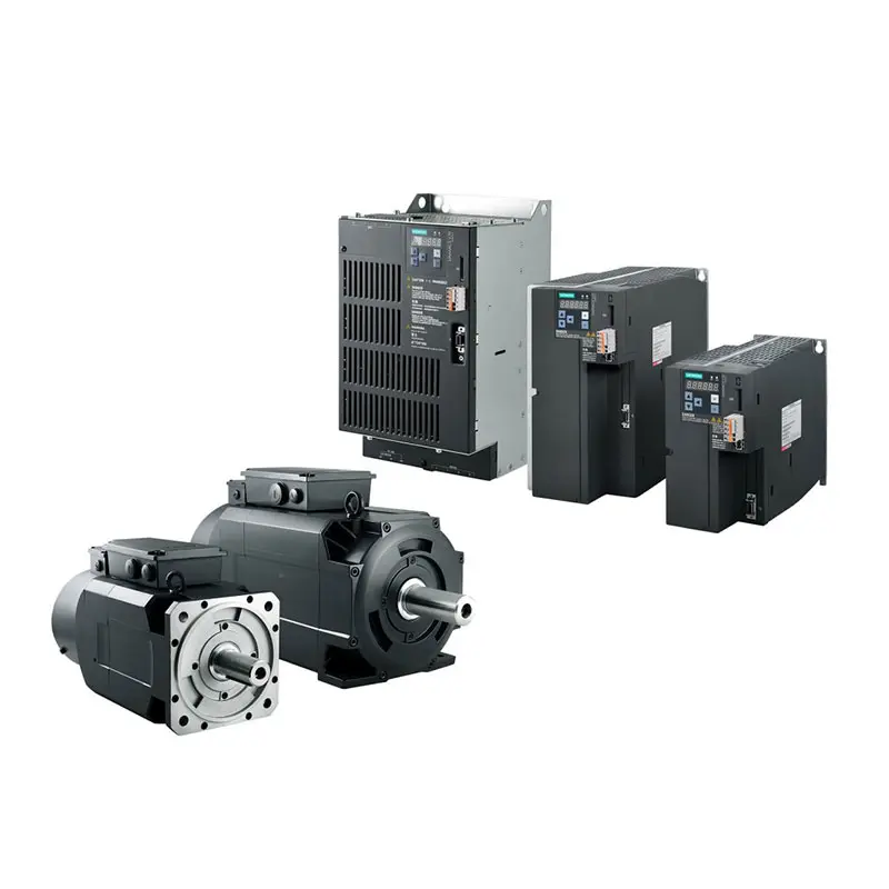 SIEMENS SINAMICS V70 Low Voltage
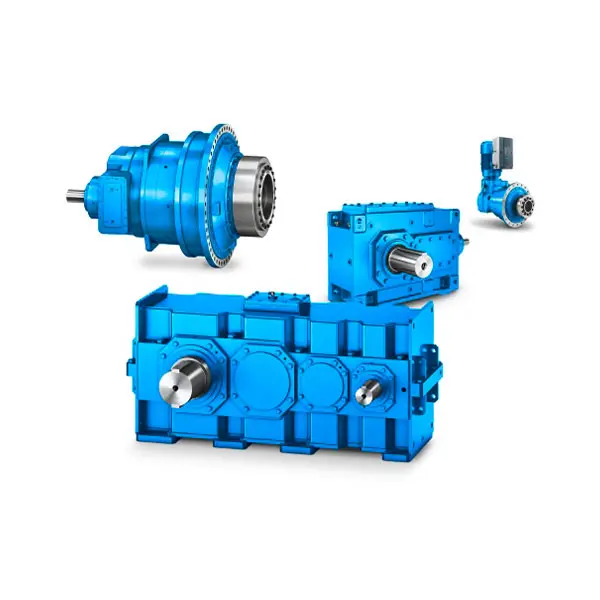 FLENDER Gear Unit
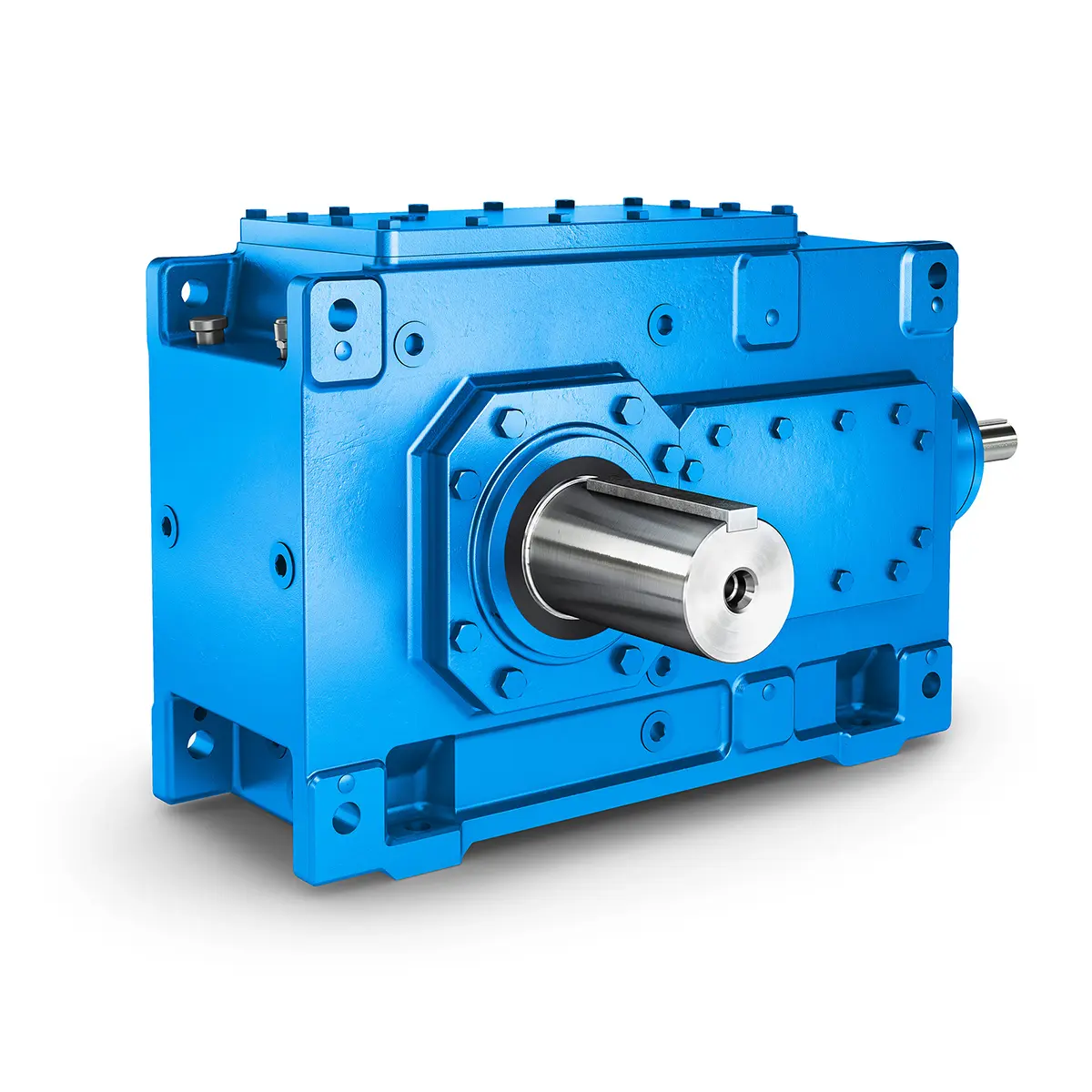 FLENDER Helical Gear Unit
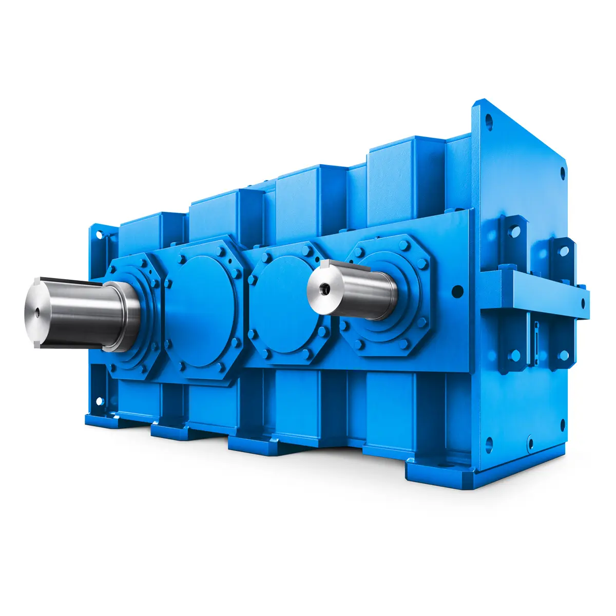 Flender gear units for lifting and luffing gears
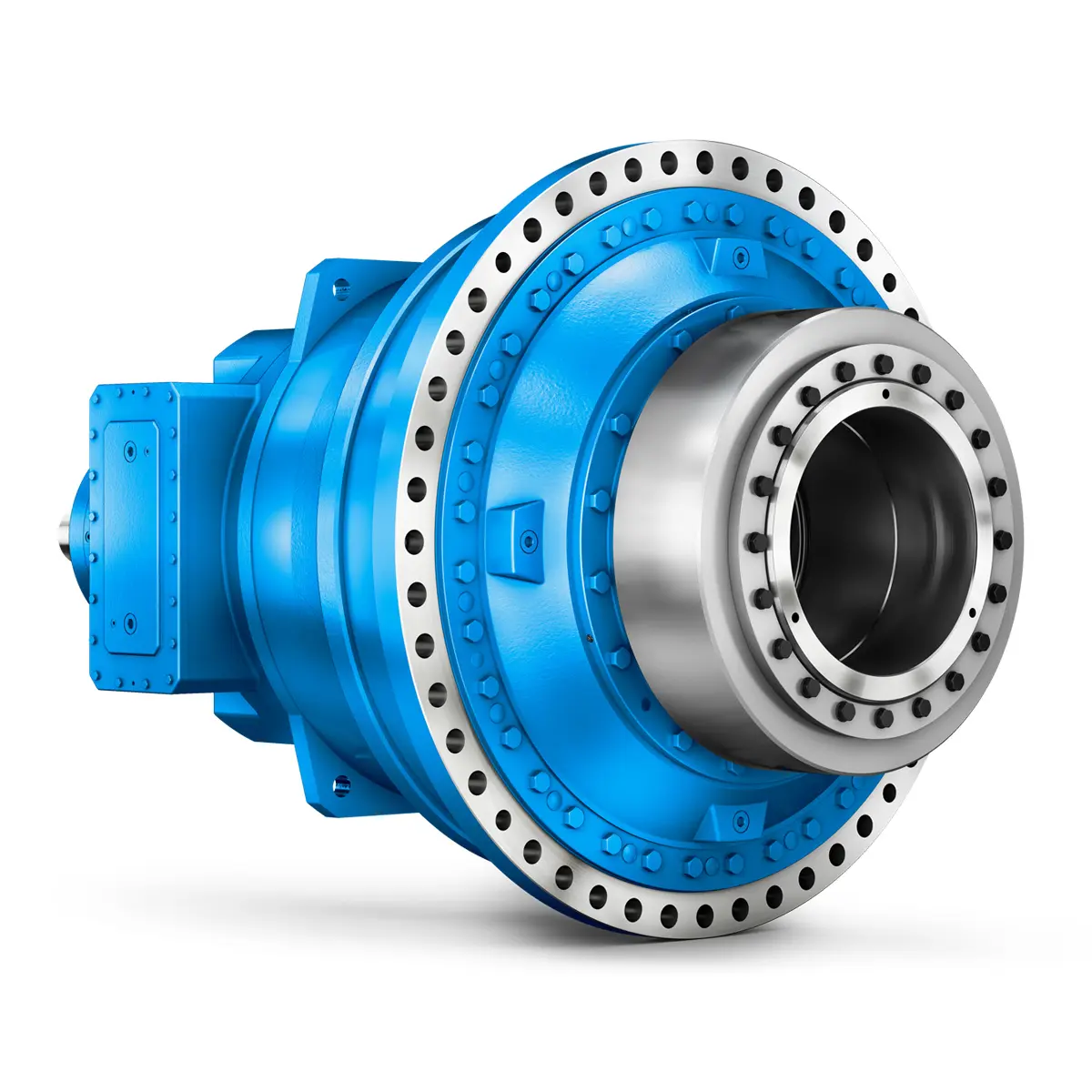 FLENDER Gear Unit gearunit gearbox
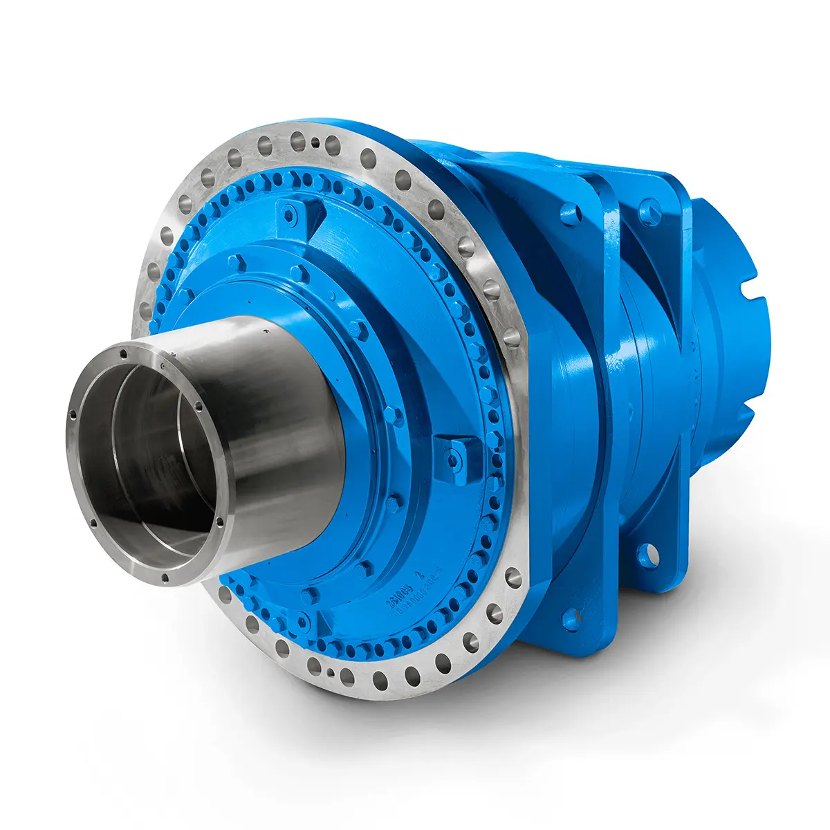 Optimal Drive Solution For Maximum Performance
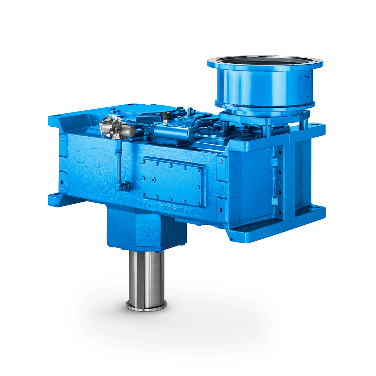 Strongly operating against biodegradable constituents
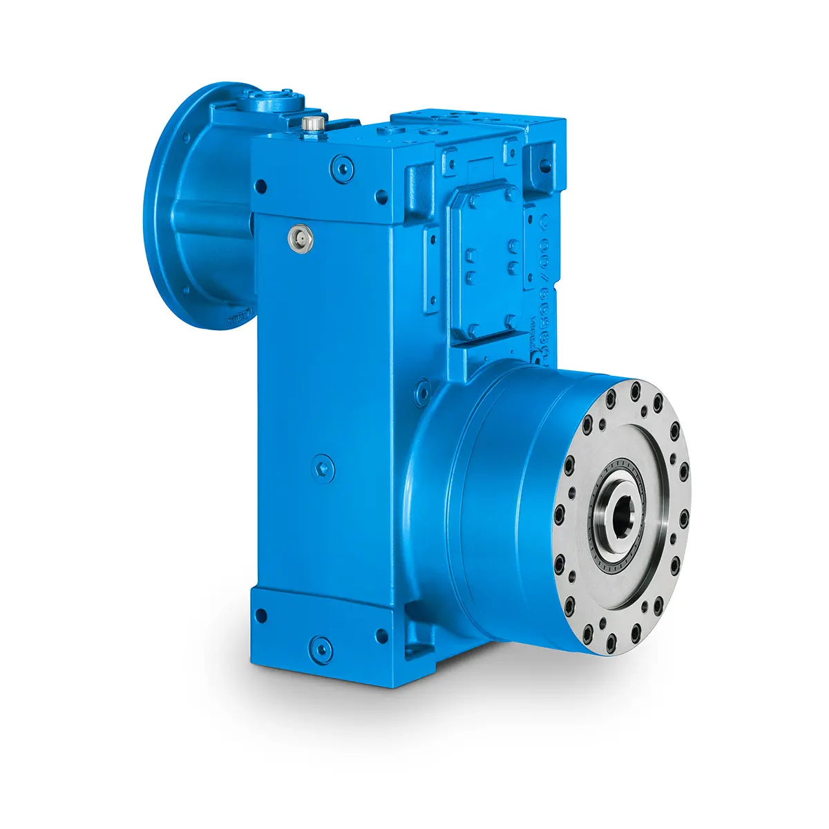 SINGLE SCREW Special industry dedicated gearunit gearbox
 Playmaker In The Premium League
 Conveyor belts gearunit gearbox
 Paper And Pulp Preparation Sections
 Operational Reliability Even In Case Of The Highest Ventilation Forces
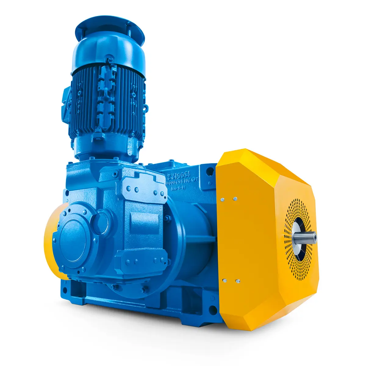 Reliable Gear Units For High Performance Vertical Conveyors 59/200
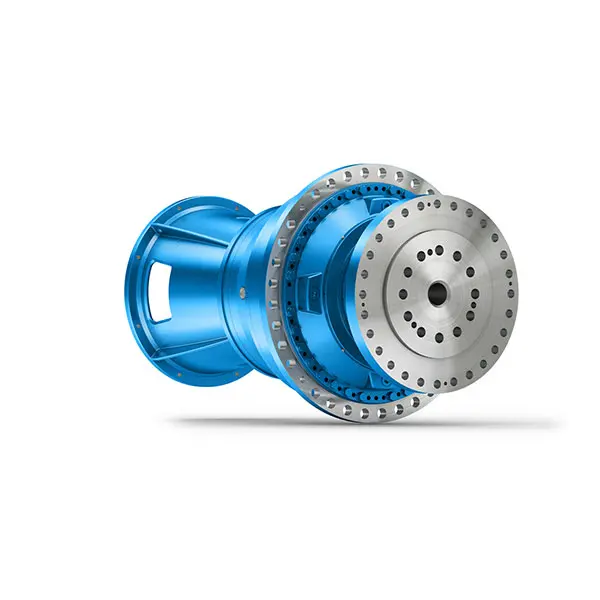 Maximum power density – PLANUREX 3 L individual drives for your sugar cane mill
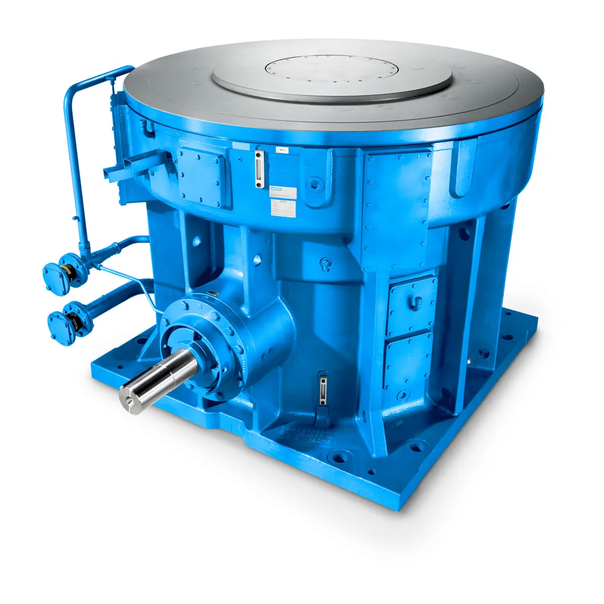 The proven all rounder gearunit gearbox
 Stirs and stirs and stirs gearunit gearbox
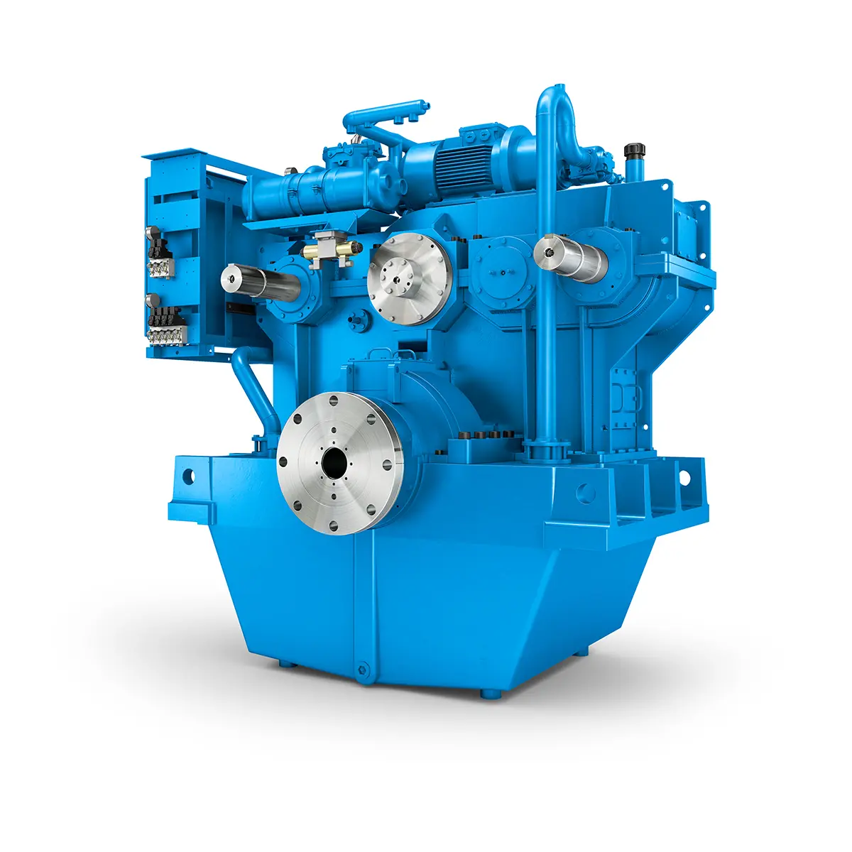 Flexibility on Board gearunit gearbox
 The right gearbox for all Multi-Engine Ships
 Reliable Power Generation on board
 Maximum performance level, fast deliverable
 Efficient and compact – FLENDER Gear Units for Sugar Mills
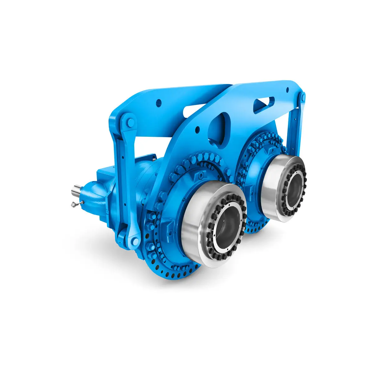 Extremely strong. Extremely compact. Extremely stressable.
 FLENDER Coupling
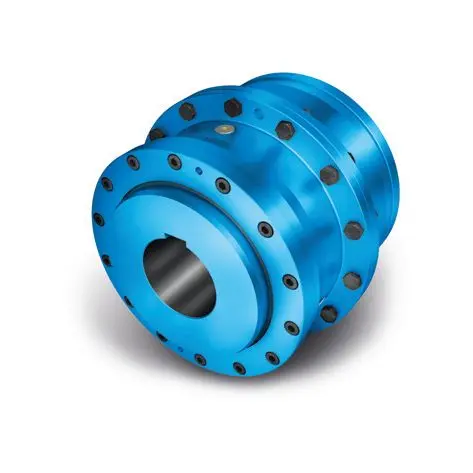 ZAPEX ZW Torsionally Rigid Gear Coupling
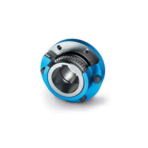 ZAPEX ZN Torsionally Rigid Gear Coupling
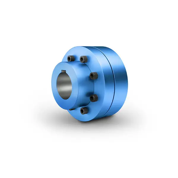 N-EUPEX Flexible high performance Coupling
 N-ARPEX Torsionally Rigid All-Steel Coupling
 ARPEX Torsionally Rigid All-Steel Coupling Spare and Parts
 RUPEX Flexible high performance Coupling
 N BIPEX Flexible high performance coupling
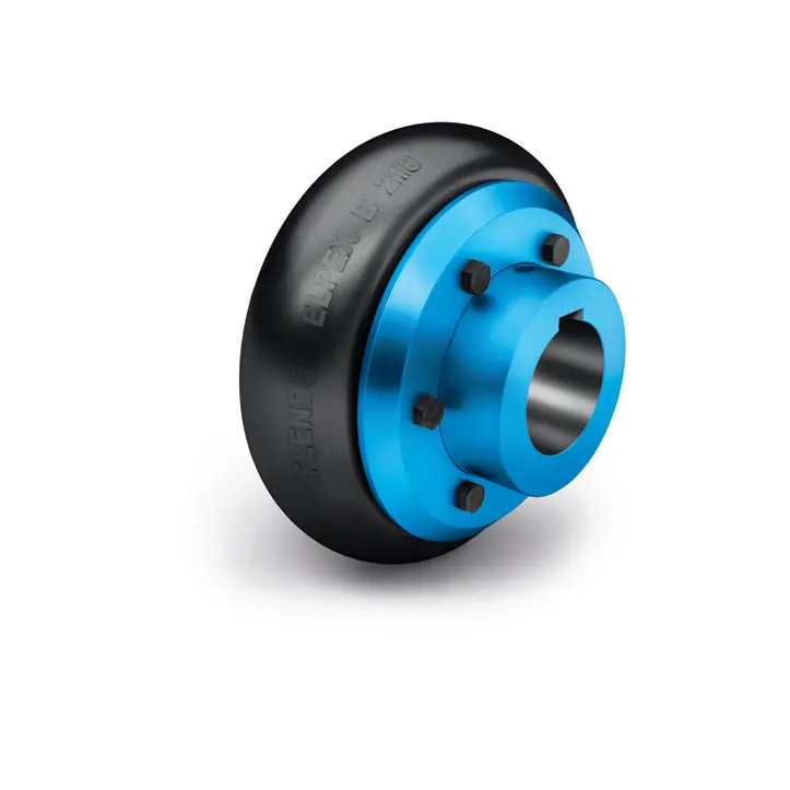 ELPEX B Highly Flexible Coupling
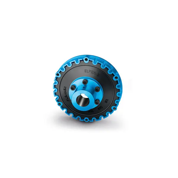 ELPEX S Highly Flexible Coupling high performance
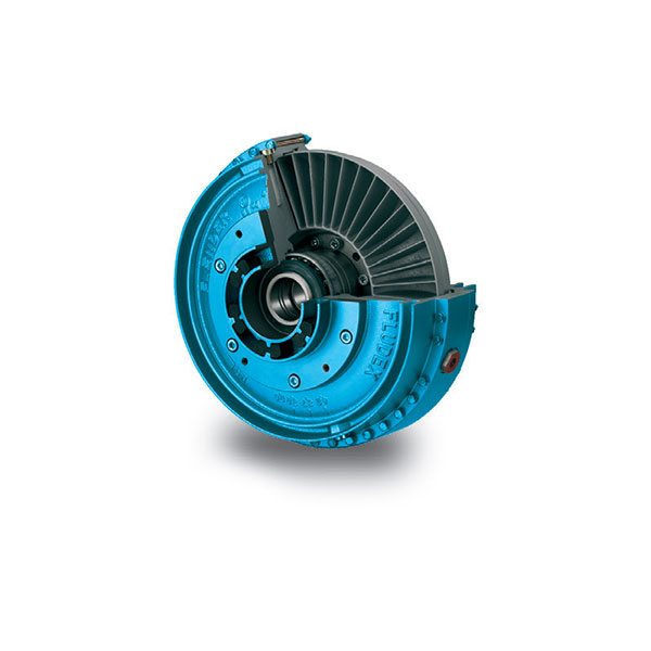 FLUDEX Fluid Coupling high performance
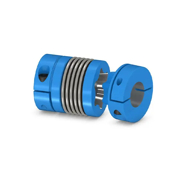 SIPEX Backlash free Coupling high performance
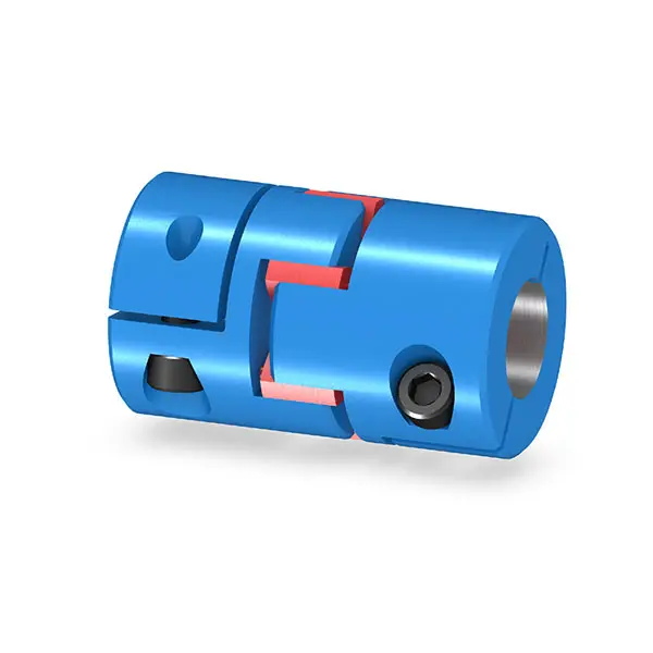 BIPEX S Backlash free Coupling high performance
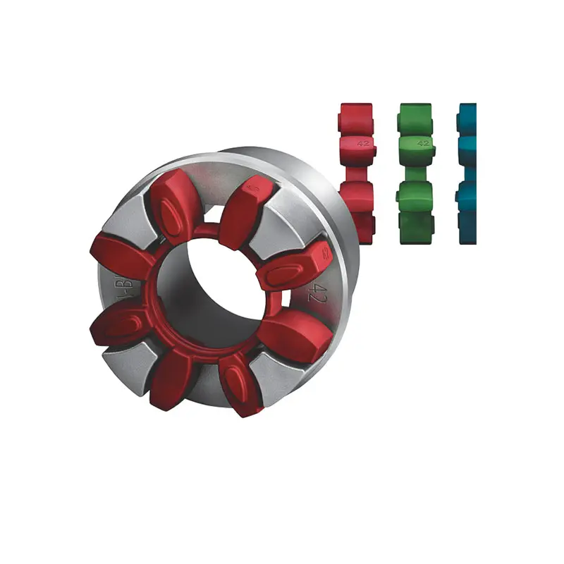 FLENDER Coupling Spare Parts high performance
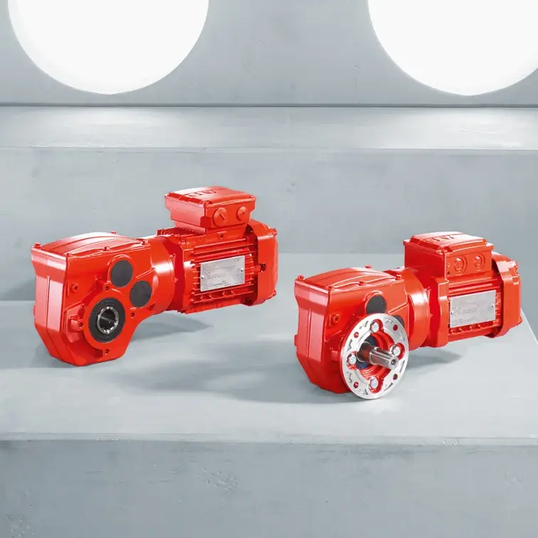 SEW Gearmotor
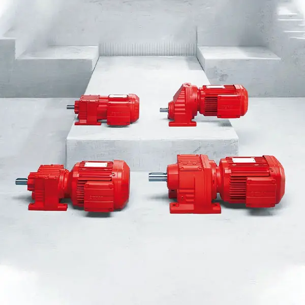 R Series Helical Gearmotor low voltage
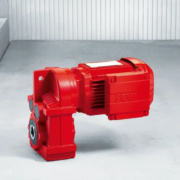 F Series Parallel Shaft Gearmotor low voltage
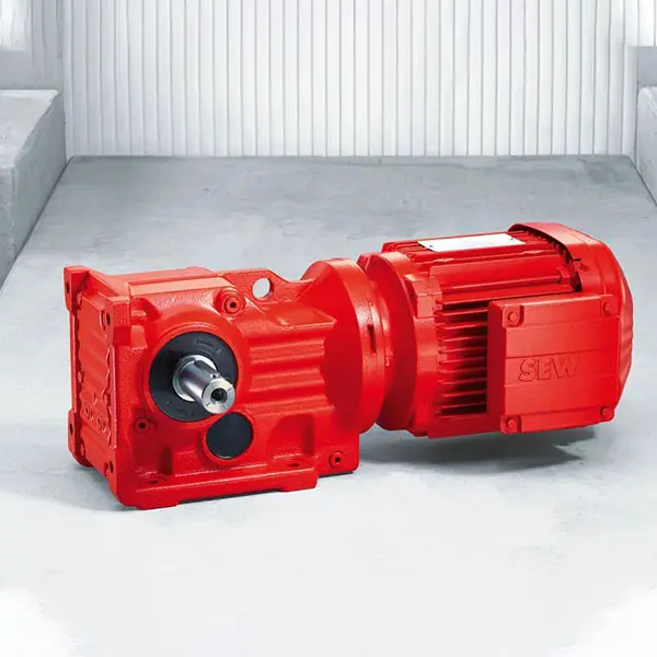 K Series Helical Bevel Gearmotor low voltage
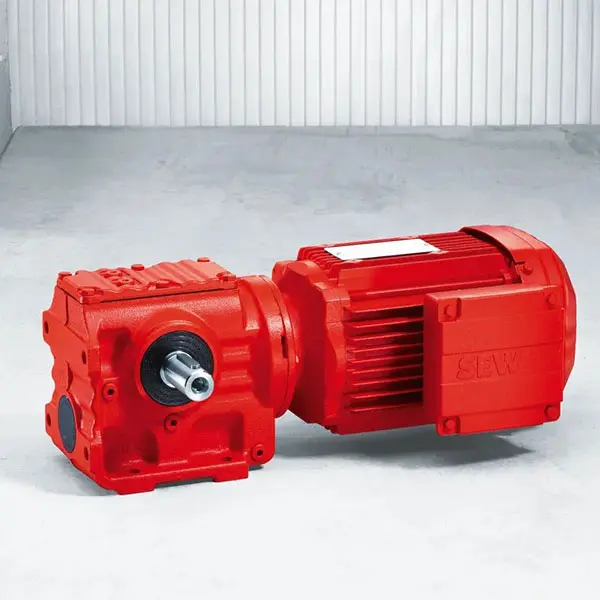 S Series Helical Worm Gearmotor low voltage
 W Series SPIROPLAN® Right Angle Gearmotor
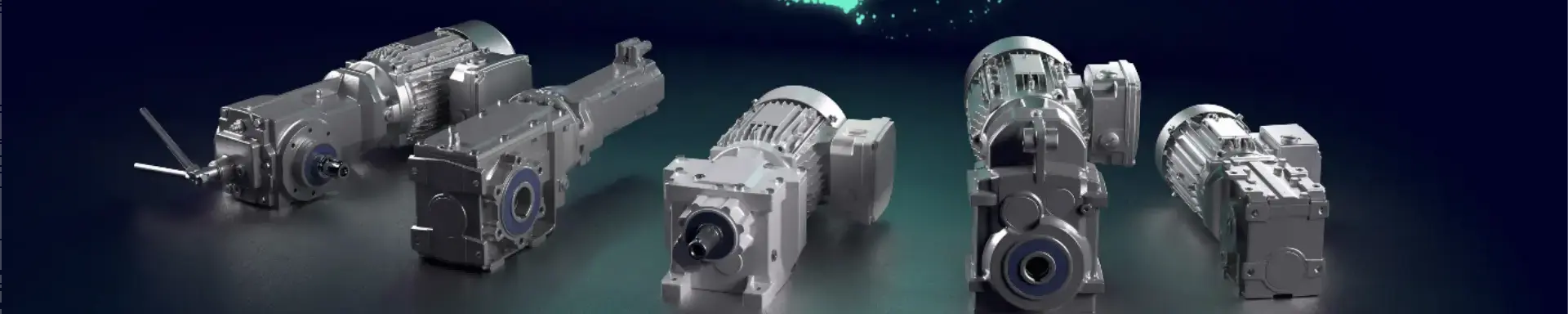
FLENDER Coupling
- SIEMENS Gearmotor
- NORD Industrial Gear Unit
- LENZE Gearmotor
- NORD Gearmotor
- SEW Planetary Gear Unit
- SEW Industrial Gear Unit
- SEW Gearmotor
- BONFIGLIOLI Precision Planetary Gearbox and Gearmotor
- BONFIGLIOLI Inverters and Servo drives
- BONFIGLIOLI Industrial Gear Unit
- BONFIGLIOLI Gearmotor
- FLENDER Coupling
- FLENDER Gear Unit
01

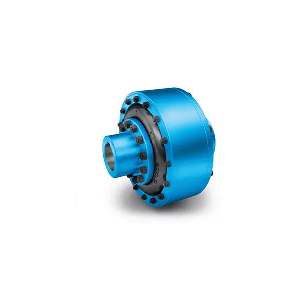
ELPEX Highly Flexible Coupling high performance
Benefits
The ELPEX coupling is suitable for horizontal and vertical mounting positions or mounting at any required angle. The coupling parts can be arranged as required on the shafts to be connected.
The split flexible rings can be changed without having to move the coupled machines.
The flexible rings are mounted without backlash and give the coupling progressive torsional stiffness, i.e. torsional stiffness increases in proportion to coupling load.
The ELPEX coupling is especially suitable for reversing operation or operation with changing directions of load.
The coupling is delivered preassembled. The flexible rings are completely assembled. On the type ENG, the coupling halves have to be bolted together after the hub has been mounted. On the type EFG, after mounting the coupling hub, only the outer flange has to be connected to the machine.
Outer flanges with different connection dimensions are available for the type EFG.
If the flexible rings are irreparably damaged or worn, the metal parts can rotate freely against one another, they are not in contact with one another.
Application
The ELPEX coupling is available in 9 sizes with a nominal torque of between 1600 Nm and 90000 Nm. The coupling is suitable for ambient temperatures of between -40 °C and +80 °C.
The ELPEX coupling is frequently used for high-quality drives which have to guarantee very long service life in harsh operating conditions.
Examples of applications are mill drives in the cement industry, marine main and secondary drives or drives on
large excavators powered by an electric motor or diesel engine.
Design and configurations
The ELPEX coupling's transmission characteristic is determined essentially by the flexible rings. The flexible rings are manufactured from a natural rubber mixture
with a multiply fabric lining. The flexible rings are split so that they can be changed without having to move the coupled machines.
The flexible rings are fastened to the hub with a clamping ring and to the outer flange with a clamping ring, using pins and bolts.
On the EFG type, the outer flange is designed with connection dimensions for connection to e.g. a diesel engine flywheel. On ENG types, the outer flange is fitted to a second hub part, which then enables the shaft-shaft connection.
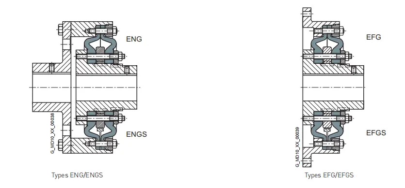
ELPEX coupling types
Type Description
ENG Coupling as shaft-shaft connection
EFG Coupling as flange-shaft connection
ENGS as ENG with fail-safe device
EFGS as EFG with fail-safe device
The following versions have already been implemented a number of times:
• ELPEX coupling with brake drum, brake disk or flywheel mass
• ELPEX coupling with axial backlash limiter
• ELPEX coupling with adapter
• ELPEX coupling in combination with a safety slip clutch
• ELPEX coupling for engaging/disengaging during standstill ELPEX coupling as part of a coupling combination
Further application-specific coupling types are available.
Dimension sheets for and information on these are available on request.
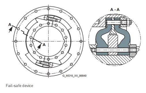
Fail-safe device of ELPEX coupling
Types ENGS and EFGS are provided with a fail-safe device.
In normal operation the torsion angle of the flexible rings is smaller than the gap between the cams. In normal operation there is no metal-metal contact.
If the flexible rings fail, cams transmit the torque from the inner part and outer part. These enable the coupling to be used in emergency mode for a short time. This option is frequently required e.g. in the case of marine drives.
Configuration
Coupling selection
The ELPEX coupling is especially suitable for rough operating environments. An application factor lower than that in Chapter introduction is therefore sufficient for all applications.
In the case of machines which excite torsional vibration, Flender urgently recommends carrying out a torsional vibration calculation or measuring the coupling load occurring in the drive.
Coupling load in continuous operation
The operating principles of the driving and driven machines are divided into categories and the application factor FB derived from these in accordance with DIN 3990-1.
Examples of torque characteristic in driven machines:
• uniform with moderate shock loads: Generators, fans, blowers
• non uniform: Reciprocating compressors, mixers, conveyor systems
• very rough: crushers, excavators, presses, mills
Coupling load under maximum and overload conditions
The maximum torque is the highest load acting on the coupling in normal operation.
Maximum torques at a frequency of up to 25 times an hour are permitted and must be lower than the maximum coupling torque. Examples of maximum torque conditions are:
Starting operations, stopping operations or usual operating conditions with maximum load.
TKmax ≥ TMax ⋅ FT
Overload torques are maximum loads which occur only in combination with special, infrequent operating conditions.
Examples of overload torque conditions are: Motor short circuit, emergency stop or blocking because of component breakage. Overload torques at a frequency of once a month are permitted and must be lower than the maximum overload torque of the coupling. The overload condition may last only a short while, i.e. fractions of a second.
TKOL ≥ TOL ⋅ FT
Coupling load due to dynamic torque load
Applying the frequency factor FF, the dynamic torque load must be lower than the coupling fatigue torque.
Dynamic torque loadTKW ≥ TW ⋅ FT ⋅ FF
Frequency of the dynamic torque load
ferr ≤ 10 Hz frequency factor FF = 1.0
Frequency of the dynamic torque load
ferr > 10 Hz frequency factor FF = √(ferr/10 Hz)
Checking the maximum speed
For all load situations nKmax ≥ nmax
Checking permitted shaft misalignment and restorative forces
For all load situations, the actual shaft misalignment must be less than the permitted shaft misalignment.
Checking bore diameter, mounting geometry and coupling design
The check must be made on the basis of the dimension tables. On request, couplings with adapted geometry can be provided.
Checking shaft-hub connection
For any information on this, please refer to Page E/20.
Checking low temperature and chemically aggressive environment
The permitted coupling temperature is specified in the
Temperature Factor FT table. In the case of chemically aggressive environments, please consult the manufacturer.
Technical specifications
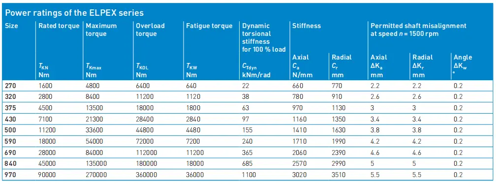
Torsional stiffness and damping
The dynamic torsional stiffness is load-dependent and increases in proportion to capacity utilization. The values specified in the selection table apply to a capacity utili zation of 100 %. The following table shows the correction factors for different rated loads.
CTdyn = CTdyn 100 % ⋅ FKC
Permitted shaft misalignment
The permitted shaft misalignment depends on the operating speed. As the speed increases, lower shaft misalignment values are permitted. The correction factors for different speeds are specified in the following table.
The maximum speed for the respective coupling size must be noted!
∆Kperm = ∆K1500 ⋅ FKV
The damping coefficient is Ψ = 1.1
Torsional stiffness also depends on the ambient temperature and the frequency and amplitude of the torsional vibration excitation. More precise torsional stiffness and damping parameters on request.
With flexible couplings the manufacturing process of the rubber elements and their aging primarily influence the stiffness value CTdyn. For this reason calculation must be made with a tolerance for the dynamic stiffness of ± 20 %.
The specified damping coefficient Ψ is a minimum value with the result that the damping performance of the coupling corresponds at least to the specified value.