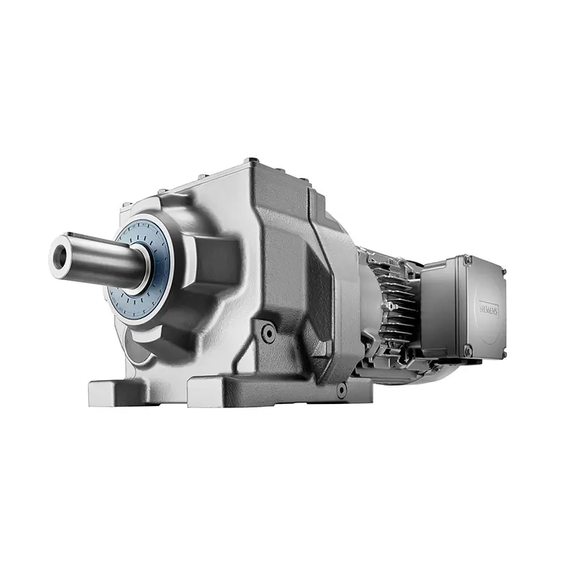
 SIEMENS Helical Gearmotor Low Voltage
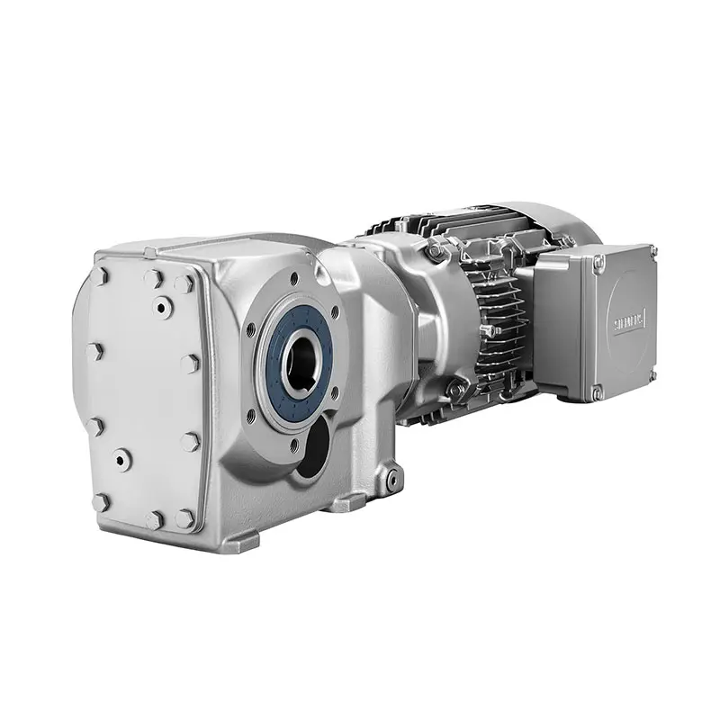 SIEMENS Bevel Helical Gearmotor
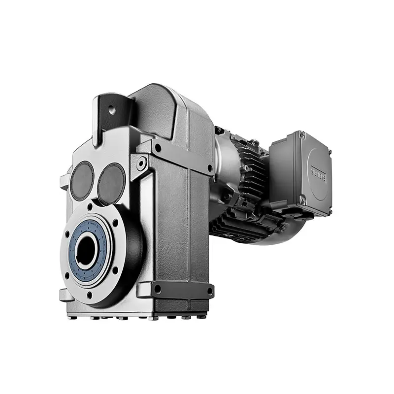 SIEMENS Parallel Shaft Gearmotor
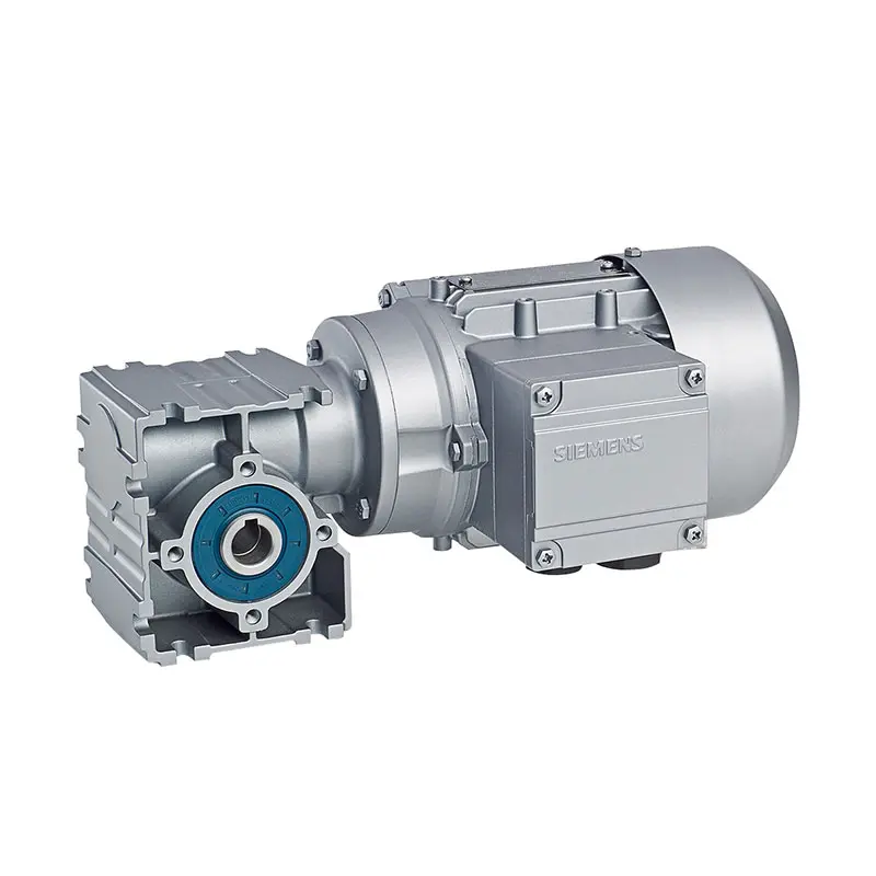 SIEMENS Worm Gearmotor Low Voltage
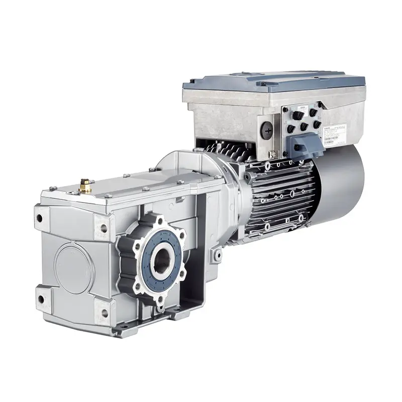 SIEMENS With Servo Motor Gearmotor
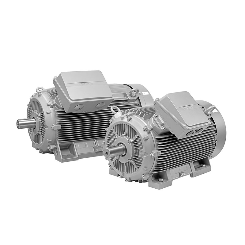 SIEMENS Low Voltage Motor Low Voltage
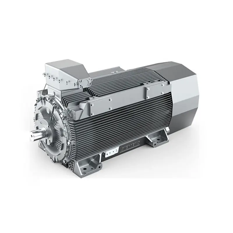 SIEMENS High Voltage Motor Low Voltage
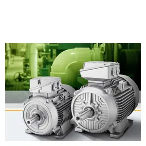 SIEMENS Marine Motor Low Voltage
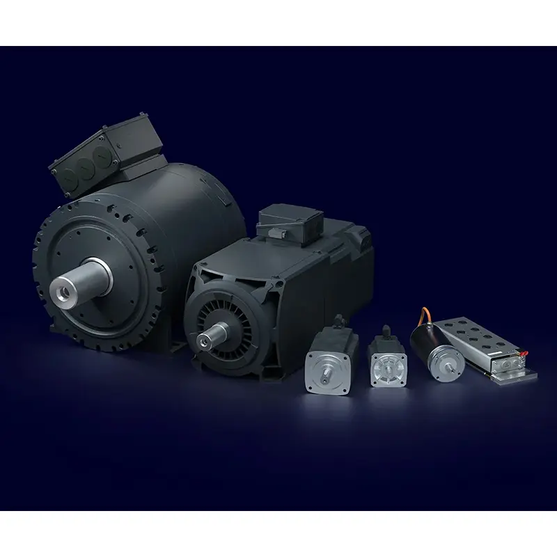 SIEMENS Servo Motor Low Voltage
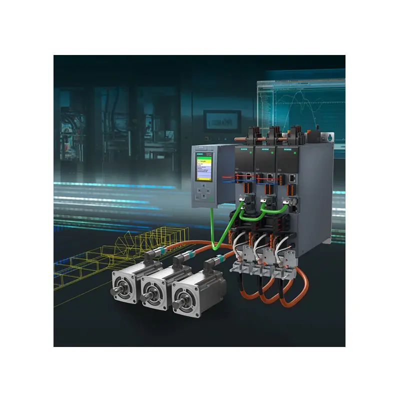 SIEMENS SINAMICS S210 Low Voltage
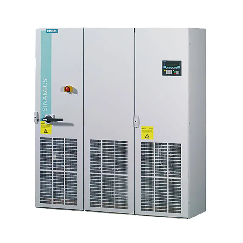 SIEMENS SINAMICS S150 Low Voltage
 SIEMENS SINAMICS S120 Low Voltage
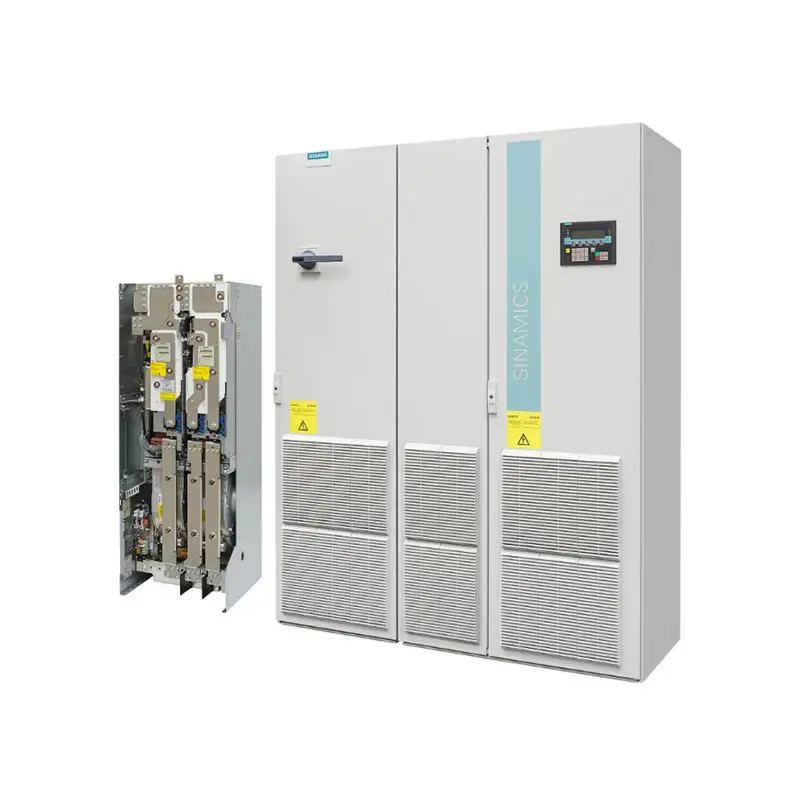 SIEMENS SINAMICS G130/G150
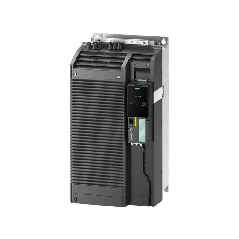 SIEMENS SINAMICS G120 Low Voltage
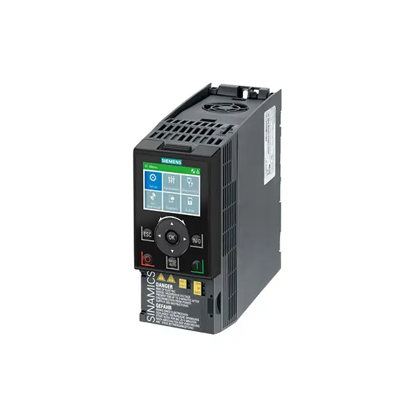 SIEMENS SINAMICS G120C Low Voltage
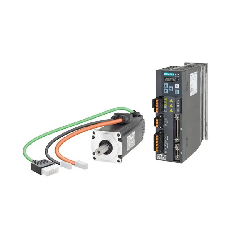 SIEMENS SINAMICS V90
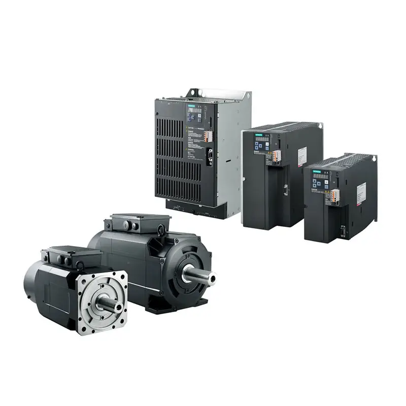 SIEMENS SINAMICS V70 Low Voltage
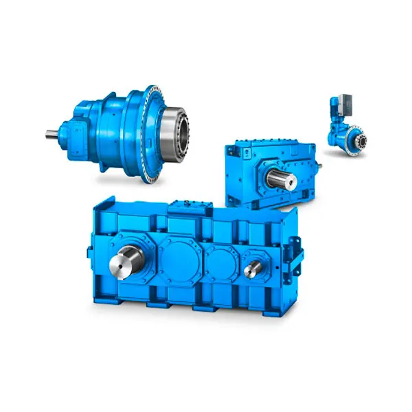 FLENDER Gear Unit
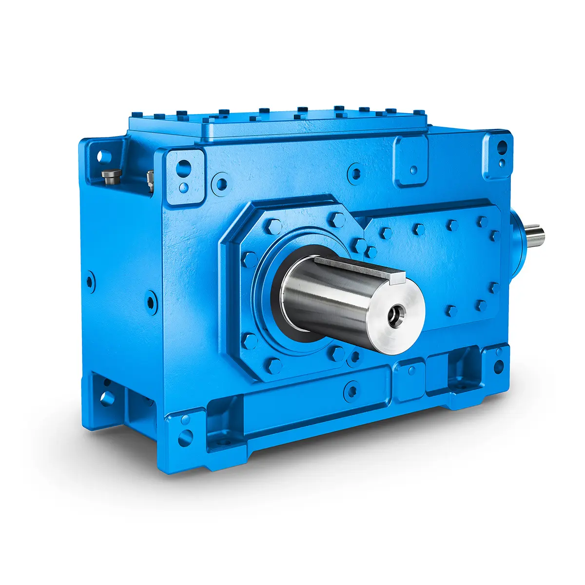 FLENDER Helical Gear Unit
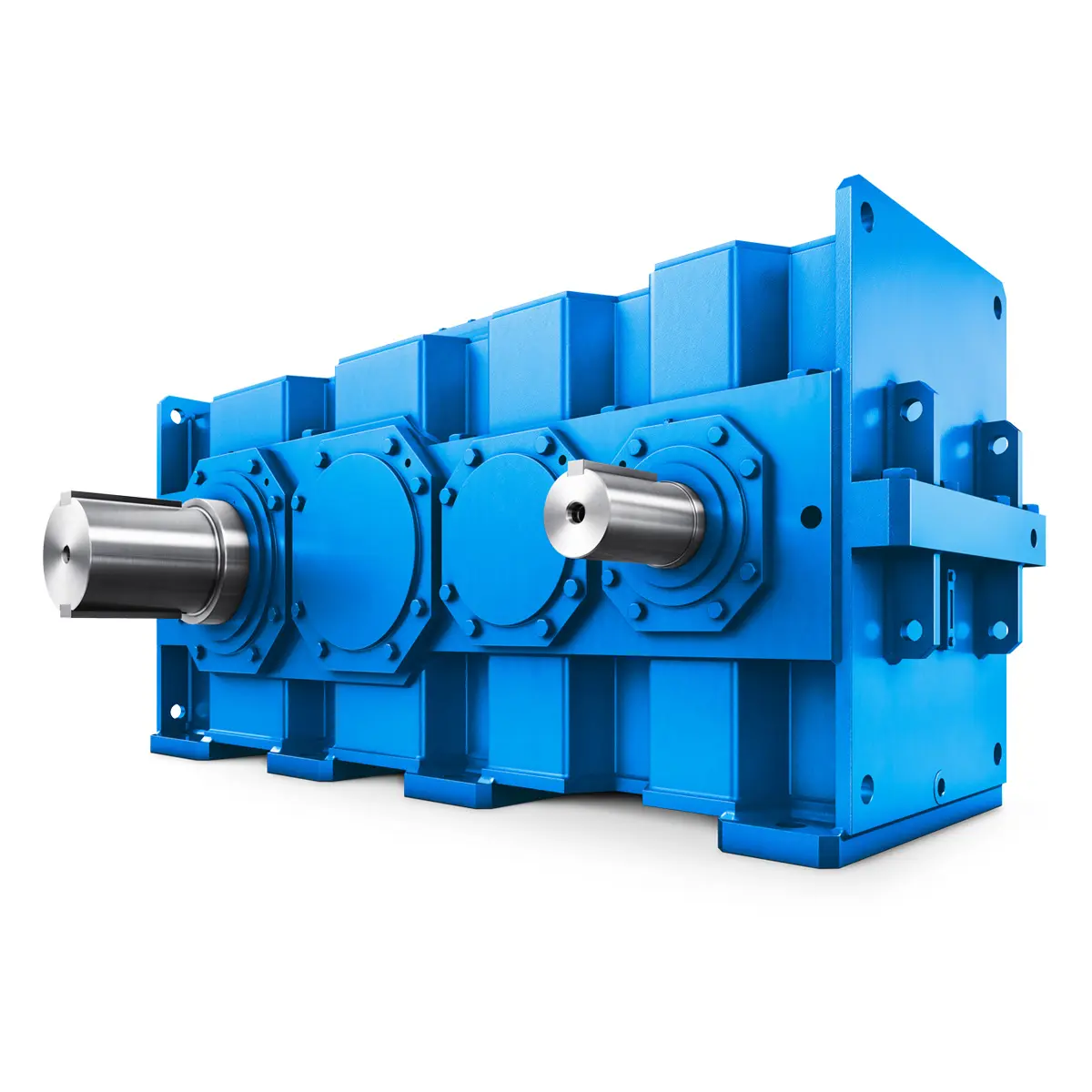 Flender gear units for lifting and luffing gears
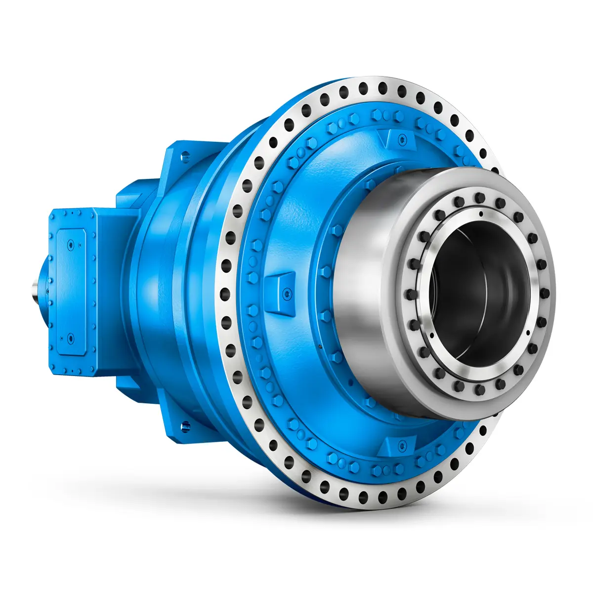 FLENDER Gear Unit gearunit gearbox
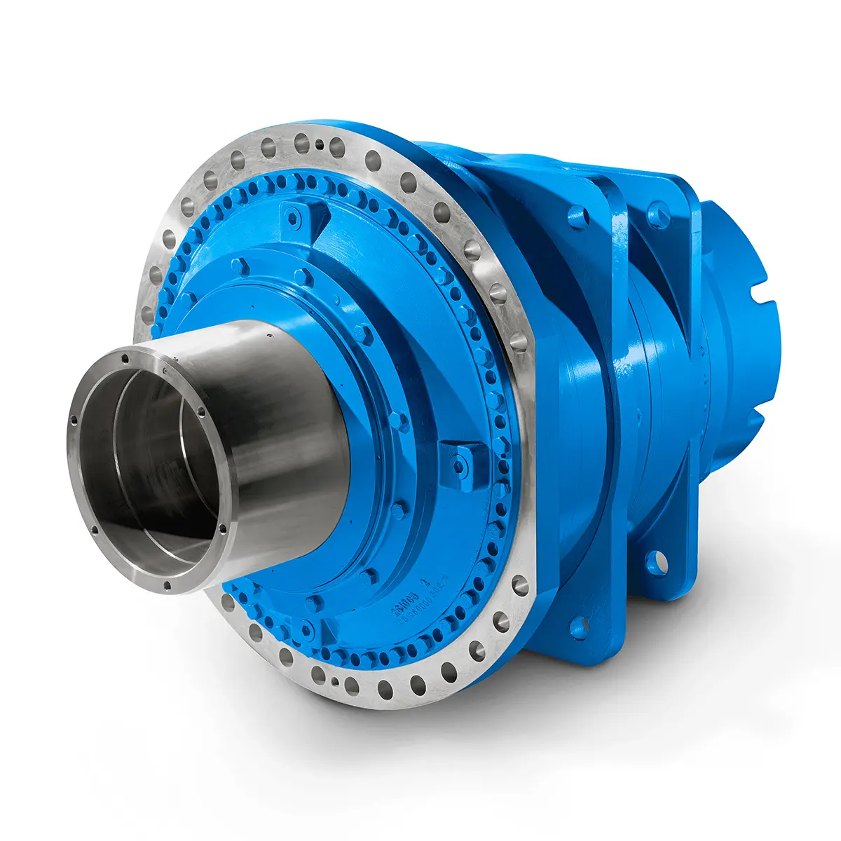 Optimal Drive Solution For Maximum Performance
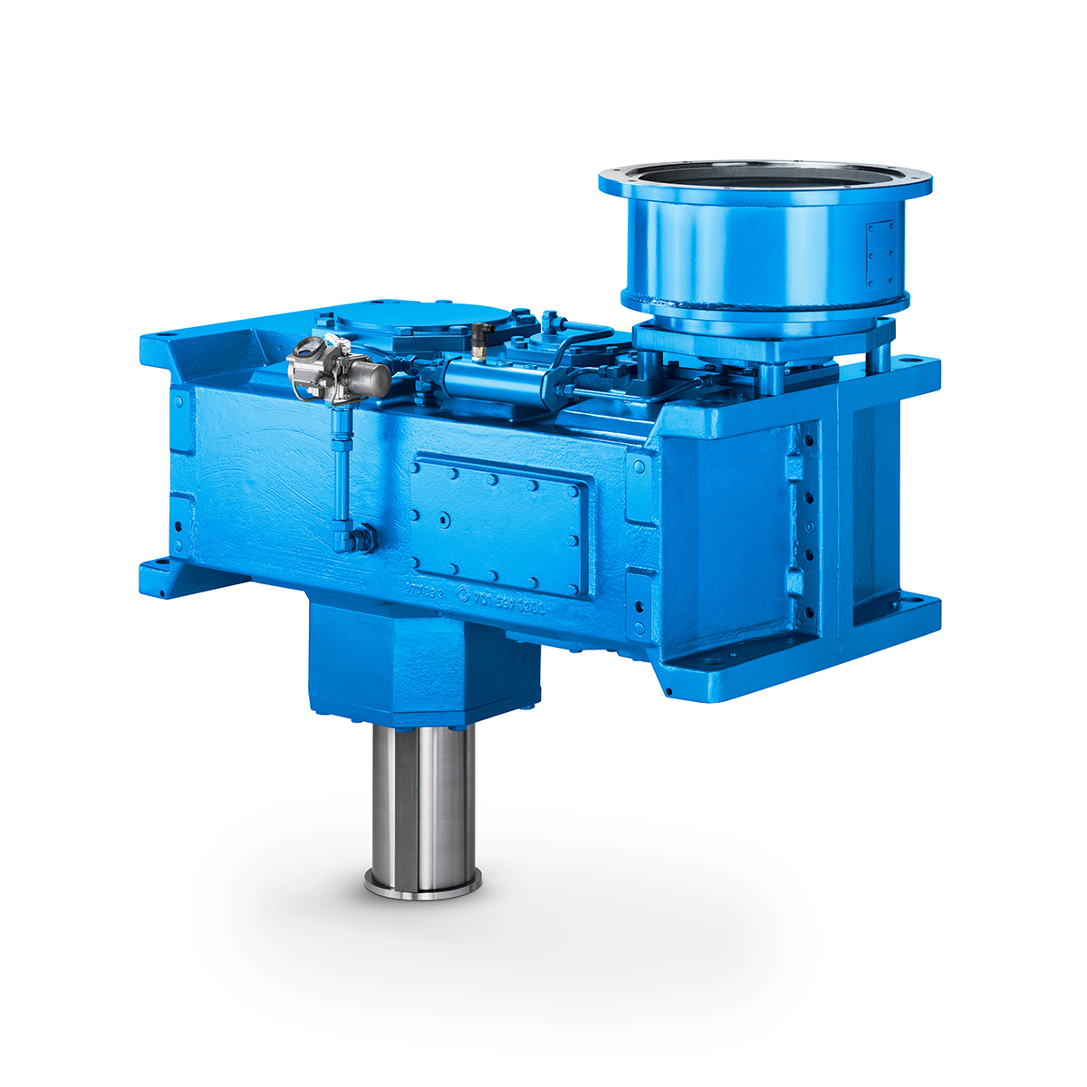 Strongly operating against biodegradable constituents
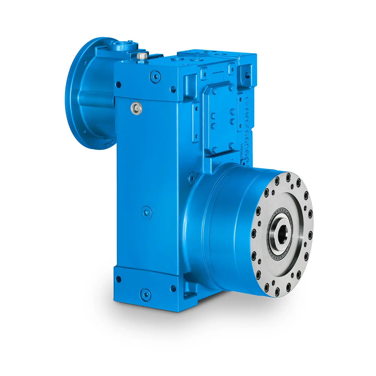 SINGLE SCREW Special industry dedicated gearunit gearbox
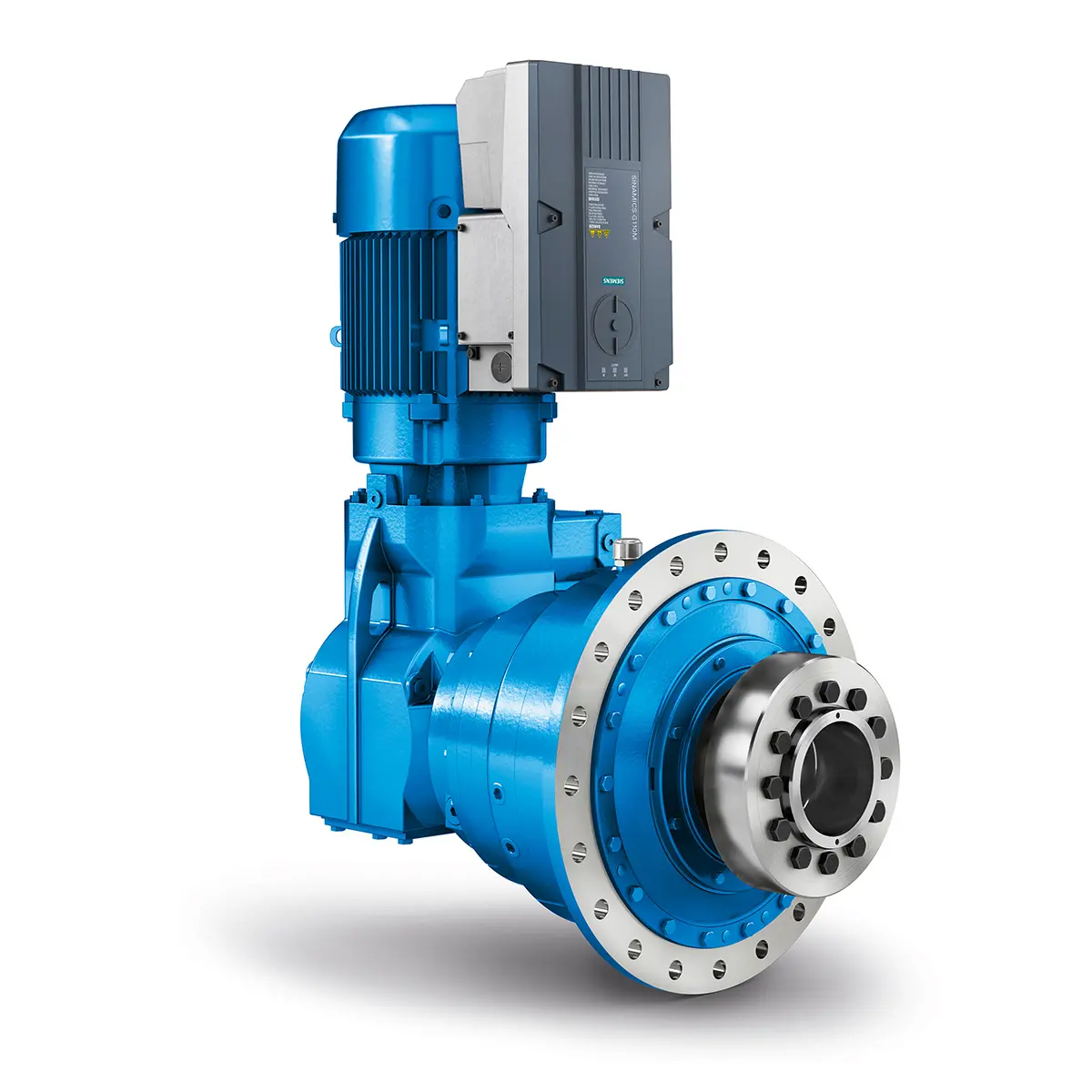 Playmaker In The Premium League
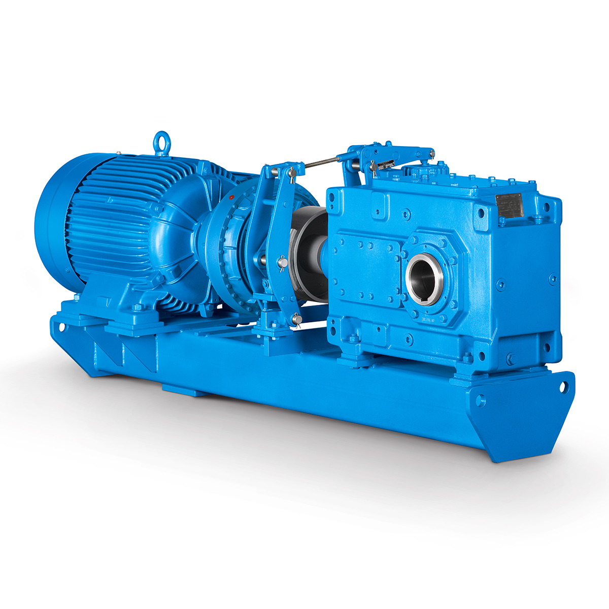 Conveyor belts gearunit gearbox
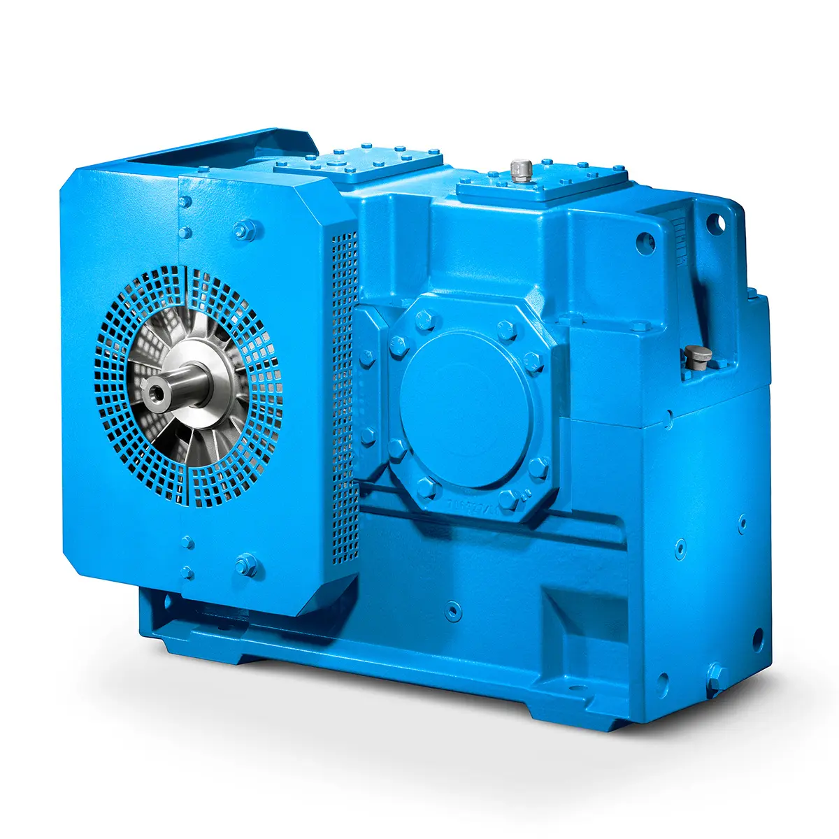 Paper And Pulp Preparation Sections
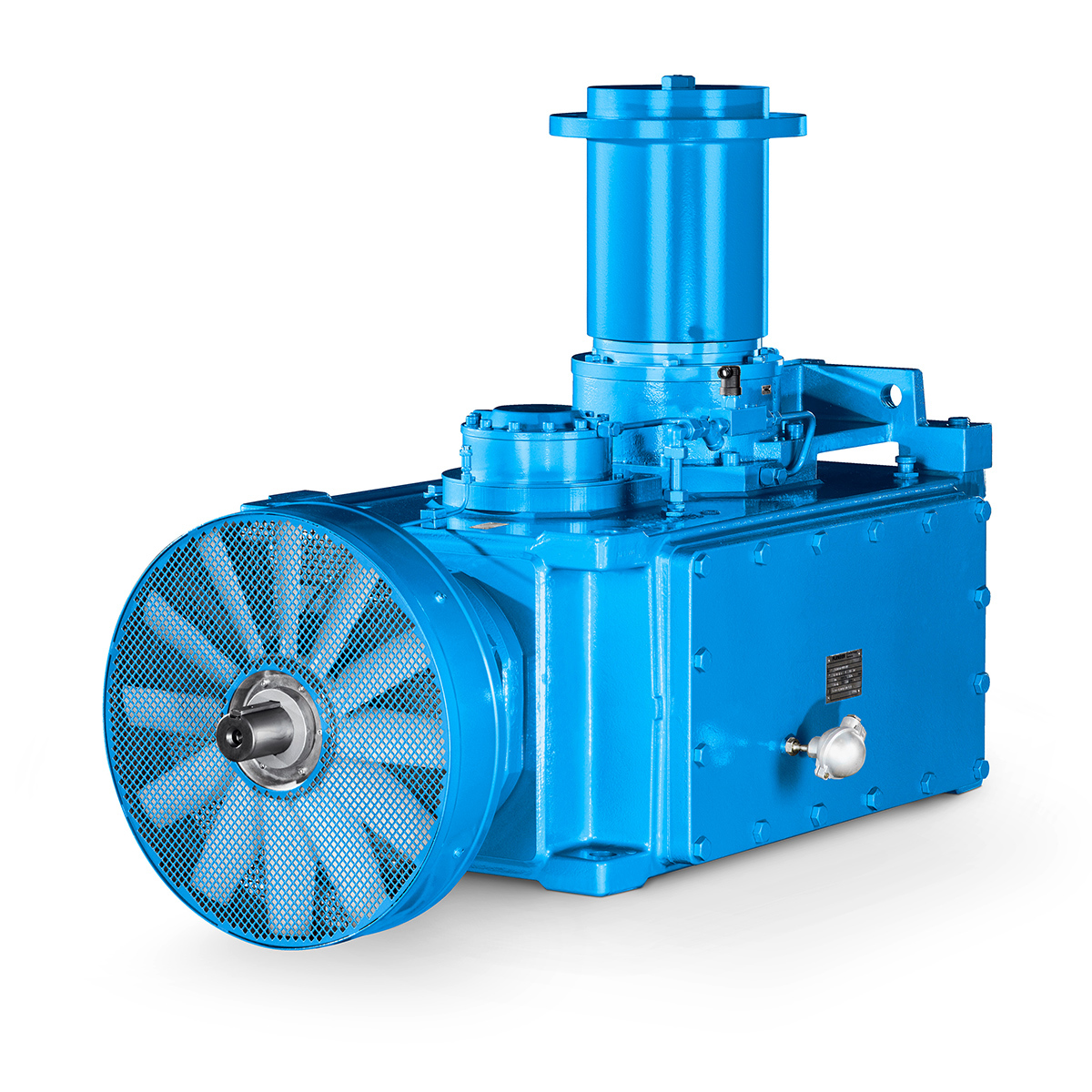 Operational Reliability Even In Case Of The Highest Ventilation Forces
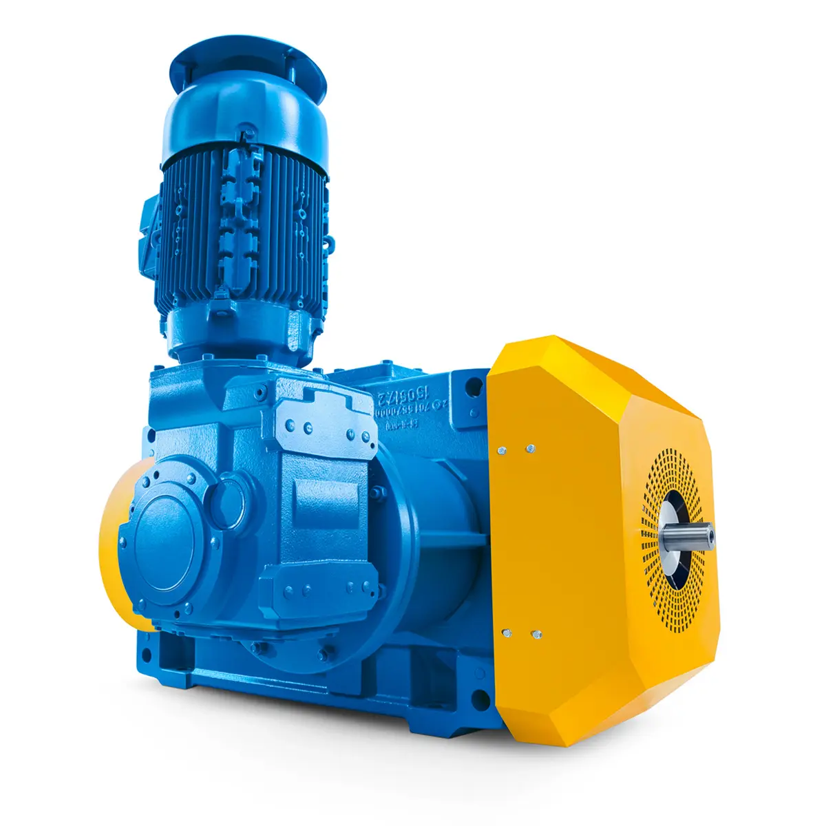 Reliable Gear Units For High Performance Vertical Conveyors 59/200
 Maximum power density – PLANUREX 3 L individual drives for your sugar cane mill
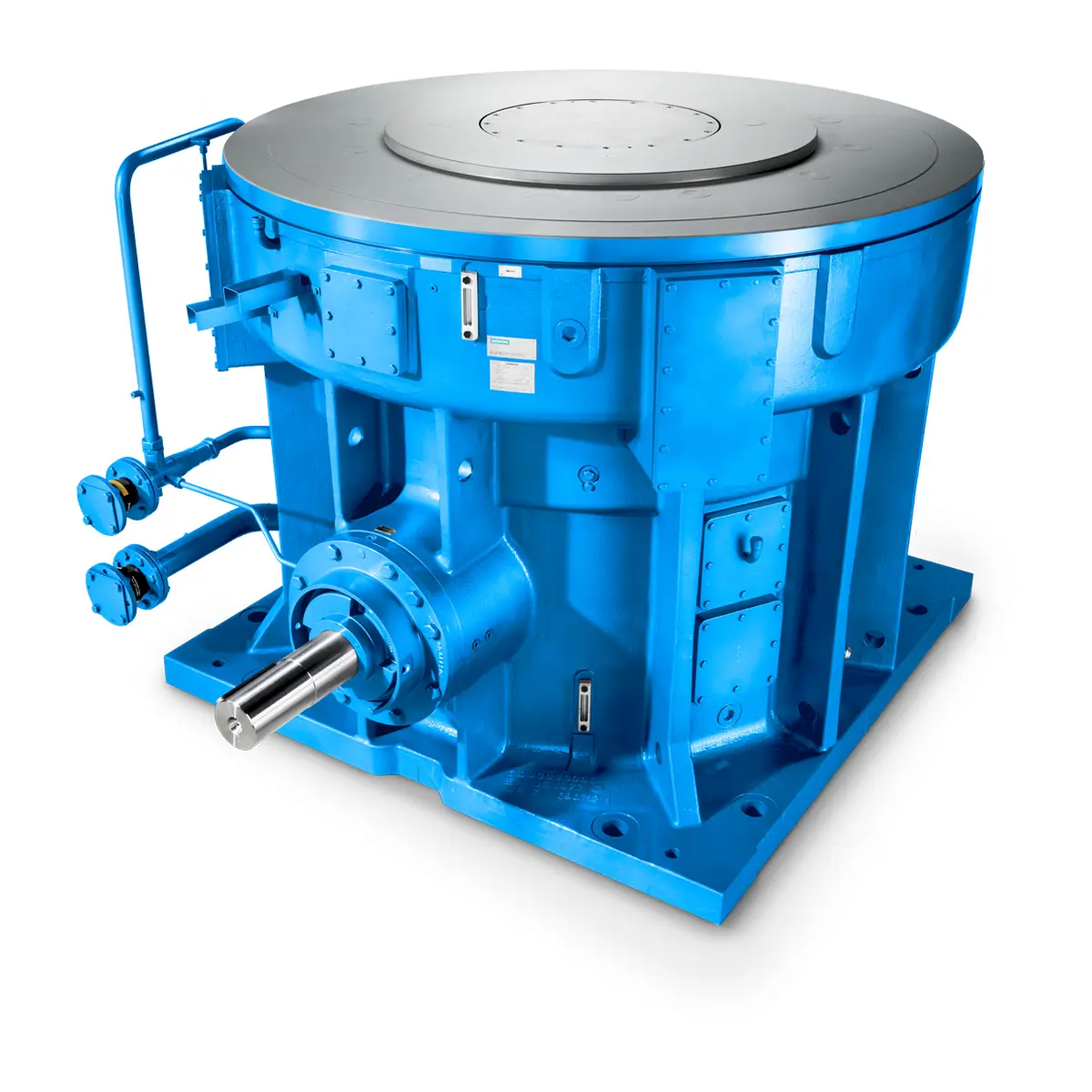 The proven all rounder gearunit gearbox
 Stirs and stirs and stirs gearunit gearbox
 Flexibility on Board gearunit gearbox
 The right gearbox for all Multi-Engine Ships
 Reliable Power Generation on board
 Maximum performance level, fast deliverable
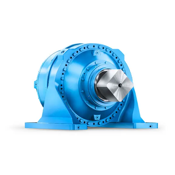 Efficient and compact – FLENDER Gear Units for Sugar Mills
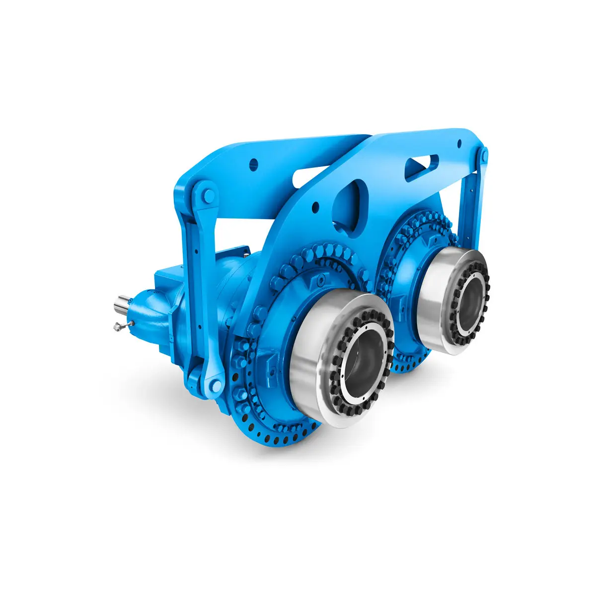 Extremely strong. Extremely compact. Extremely stressable.
 FLENDER Coupling
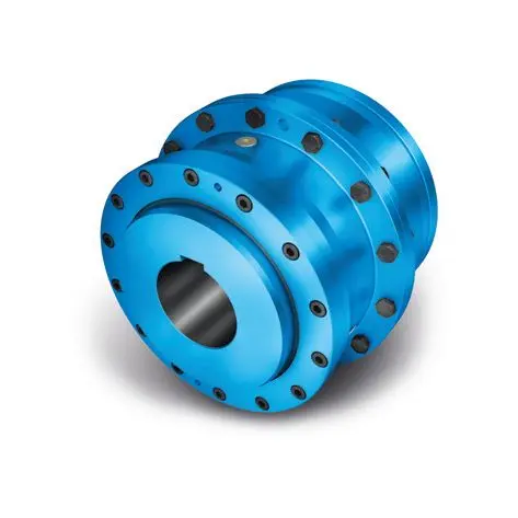 ZAPEX ZW Torsionally Rigid Gear Coupling
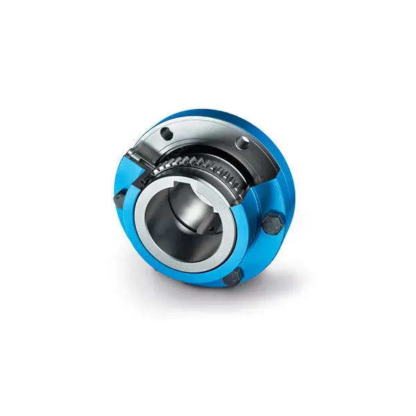 ZAPEX ZN Torsionally Rigid Gear Coupling
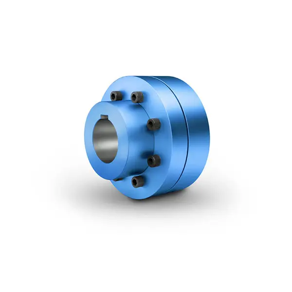 N-EUPEX Flexible high performance Coupling
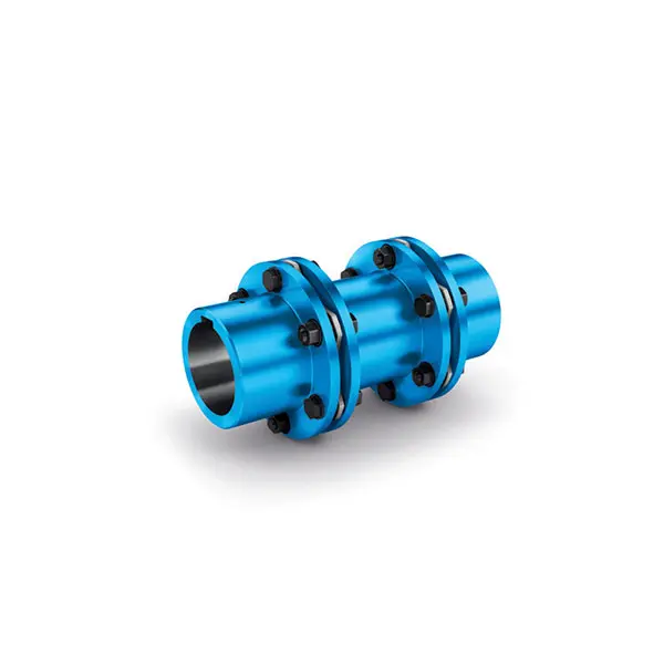 N-ARPEX Torsionally Rigid All-Steel Coupling
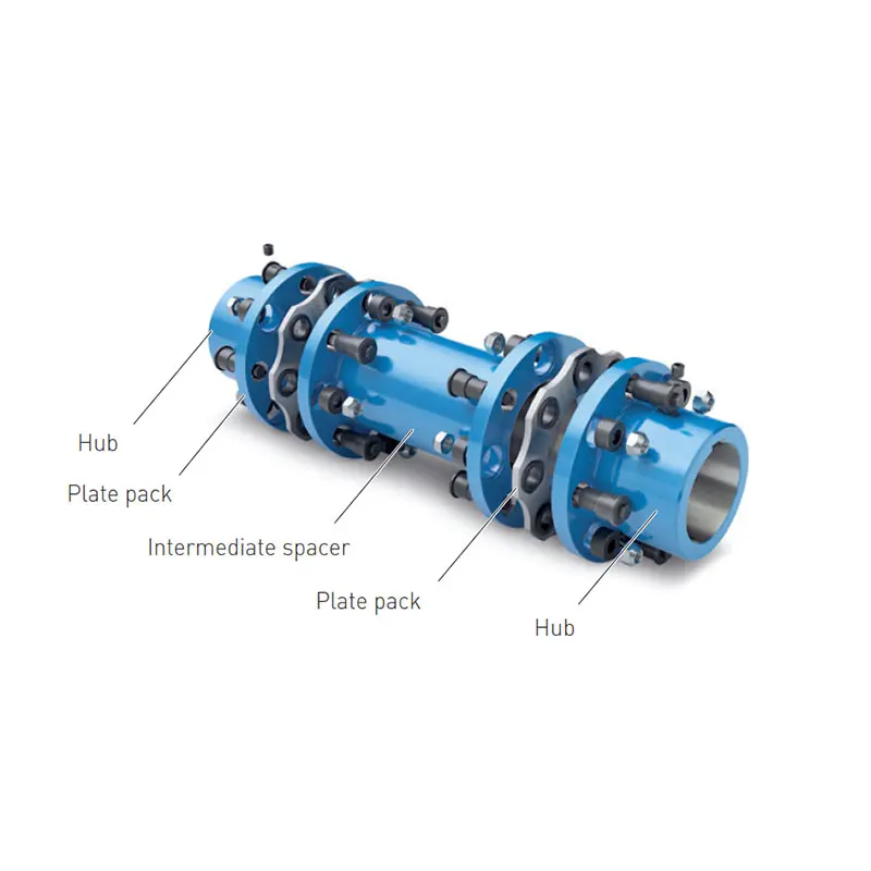 ARPEX Torsionally Rigid All-Steel Coupling Spare and Parts
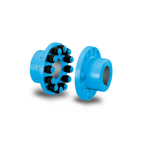 RUPEX Flexible high performance Coupling
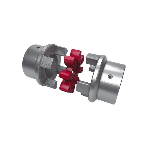 N BIPEX Flexible high performance coupling
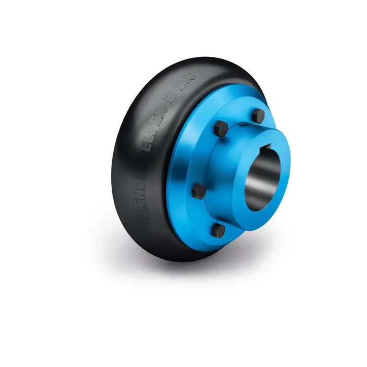 ELPEX B Highly Flexible Coupling
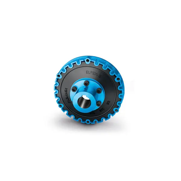 ELPEX S Highly Flexible Coupling high performance
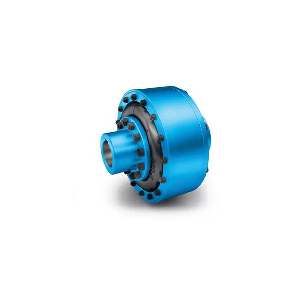 ELPEX Highly Flexible Coupling high performance
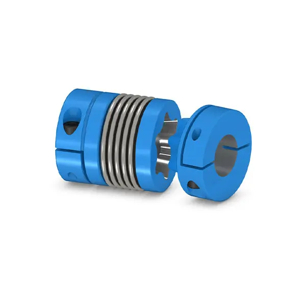 SIPEX Backlash free Coupling high performance
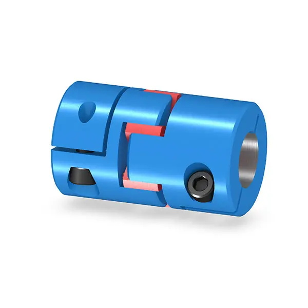 BIPEX S Backlash free Coupling high performance
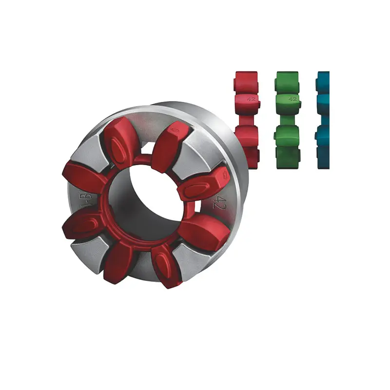 FLENDER Coupling Spare Parts high performance
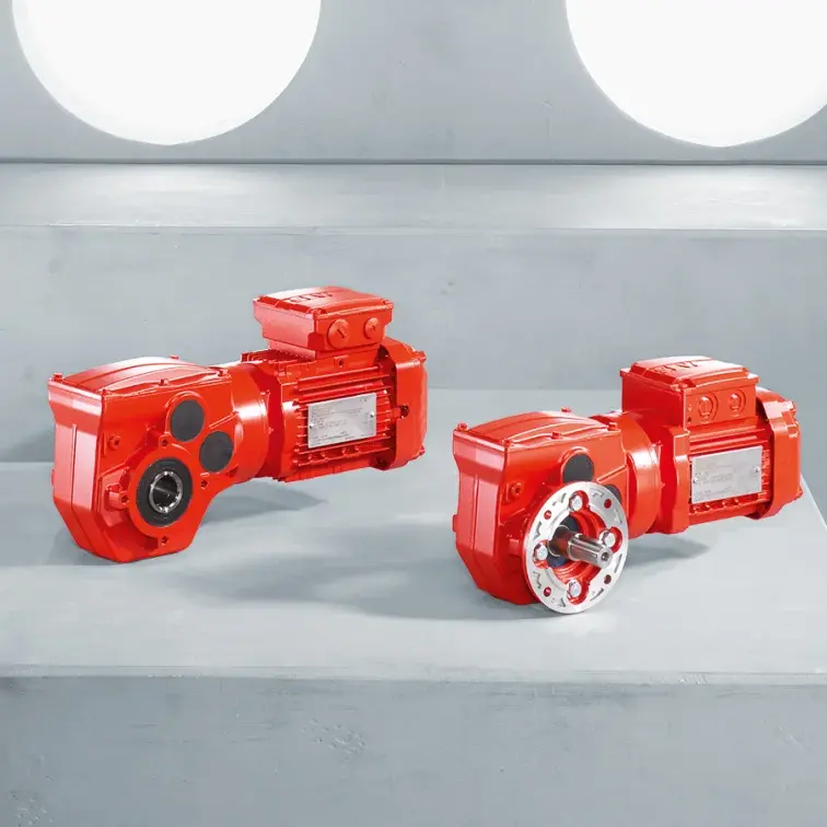 SEW Gearmotor
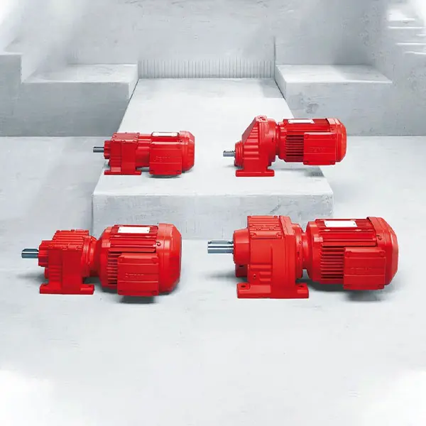 R Series Helical Gearmotor low voltage
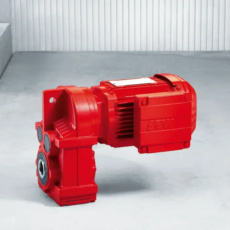 F Series Parallel Shaft Gearmotor low voltage
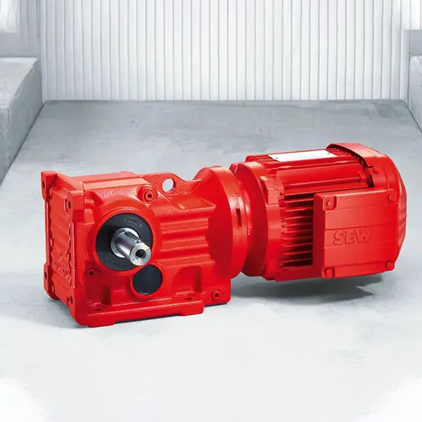 K Series Helical Bevel Gearmotor low voltage
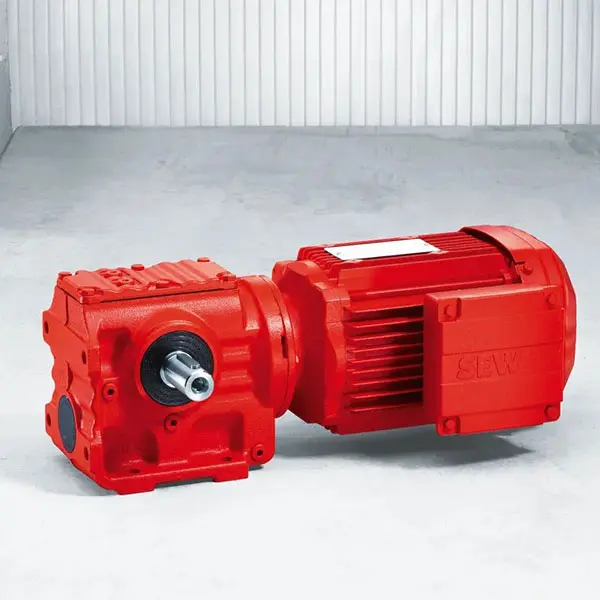 S Series Helical Worm Gearmotor low voltage
 W Series SPIROPLAN® Right Angle Gearmotor
FLENDER Coupling
- SIEMENS Gearmotor
- NORD Industrial Gear Unit
- LENZE Gearmotor
- NORD Gearmotor
- SEW Planetary Gear Unit
- SEW Industrial Gear Unit
- SEW Gearmotor
- BONFIGLIOLI Precision Planetary Gearbox and Gearmotor
- BONFIGLIOLI Inverters and Servo drives
- BONFIGLIOLI Industrial Gear Unit
- BONFIGLIOLI Gearmotor
- FLENDER Coupling
- FLENDER Gear Unit
01

FLUDEX Fluid Coupling high performance
Benefits
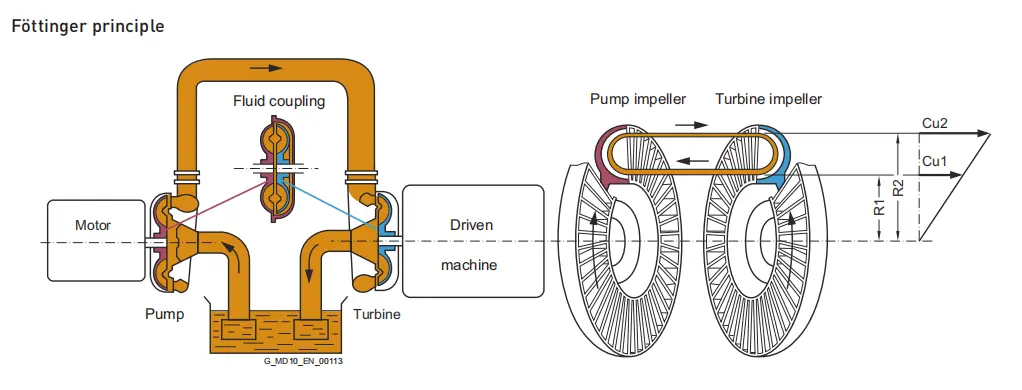
FLUDEX couplings are hydrodynamic fluid couplings which operate on the Föttinger principle. The coupling parts on the input and output sides are not mechanically connected to each other. Output is transmitted via the oil filling which rotates in the coupling and is conducted over radially arranged blades.
FLUDEX couplings limit starting and maximum torque in the drive train and, through the property of rotational slip, serve as an aid to starting the motor, as overload protection in the event of fault and for isolating torsional vibration.
When large masses are started up, the drive train is accelerated only at the torque determined by the coupling characteristic. The starting operation is spread over time, the driven machine started softly and smoothly.
In the case of special operating conditions, such as overload or blocking of the driven machine, the FLUDEX coupling limits the maximum torque load and prevents the inert effect of the rotating motor mass on the drive train.
The coupling then acts as a load-holding safety clutch until the drive is shut off by the motor control or coupling monitoring system.
The FLUDEX coupling further acts as a means of decoupling during torsional vibration excitation.
Torsional vibration excitation with a frequency of > 5 Hz is virtually absorbed by the coupling.
To compensate for shaft misalignment, the FLUDEX coupling is combined with a displacement coupling e.g. of the N-EUPEX type.
All FLUDEX couplings are designed with radial unset blades and are therefore suitable for rotation in both directions and reversing operation. They can be fitted horizontally, at an angle or vertically. In the case of
FLUDEX couplings with a delay chamber it must be ensured, when fitting at an angle or vertically, that the delay chamber is below the working chamber.
The split flexible rings can be changed without having to move the coupled machines.
Application
FLUDEX couplings are used in drives for conveyor systems such as belt conveyors, bucket elevators and chain conveyors. In heavy industry FLUDEX couplings are used for applications such as blade wheel drives, crushers, roller presses, mixers, large ventilators, boiler feed pumps, large compressors, centrifuges and auxiliary drives for mills.
Further applications are, for example, pump drives, PTO generator drives, wind power systems and door and gate drives.
In drives with diesel engines, FLUDEX couplings are used on driven machines with a high mass moment of inertia.
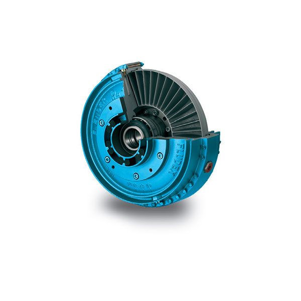
Design and configurations
FLUDEX couplings are constructed of just a few, robust components. Internal components include the hollow shaft or solid shaft (106), to which the blade wheel (105) is connected. The outer housing comprises the cover (102) and the blade wheel housing (101). The joint is constructed as a bolted flange joint and sealed with an O ring. The outer housing and the shaft or hollow shaft have double bearing support and are sealed off to the outside with radial shaft seals. The coupling is provided with two filler plugs (153) with integral overflow protection and with one or two fusible safety plugs (103) in the coupling housing for protection against overheating. The fusible safety plug or a screw plug fitted in the same position also serves as a fluid drain plug and with the aid of a scale marking on the housing can be used as a level indicator.
Materials
• Blade wheel and housing: Cast aluminum AlSi10Mg or AlSi9Mg
• Shaft and hollow shaft: Steel with a yield point higher than 400 N/mm2
• Static seals and radial shaft seals: Perbunan NBR or Viton FPM
• Add-on parts: Grey cast iron EN-GJL-250, spheroidal graphite cast iron
EN-GJS-400 or steel
Fusible safety plugs
If a FLUDEX coupling is operated with an impermissibly high slip for a prolonged period, the oil filling and the coupling housing will overheat. Fusible safety plugs which release the oil filling into the environment upon reaching a preset temperature are therefore fitted in each coupling housing. These protect the coupling from irreparable damage through overheating or overpressure and disconnect the drive motor from the driven machine.
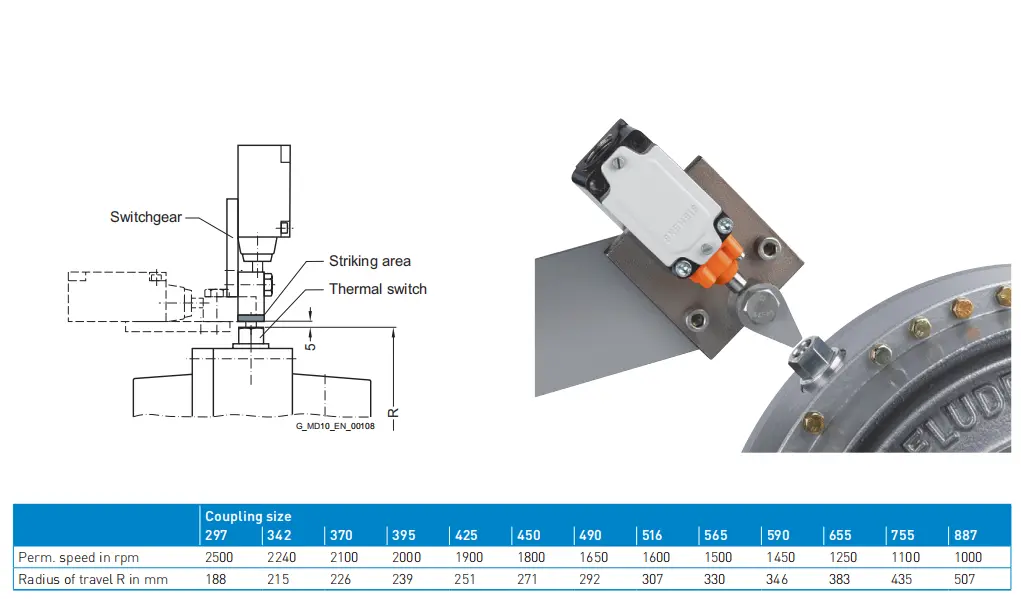
Thermal switching equipment
By adding thermal switching equipment leakage and loss of the hydraulic fluid as well as a risk to and contamination of the environment in the event that the coupling overheats can be avoided.
The thermal switching equipment does not work if a machine side is blocked and the coupling housing is connected to this side. If the coupling is stationary, the switching pin cannot actuate the switching equipment.
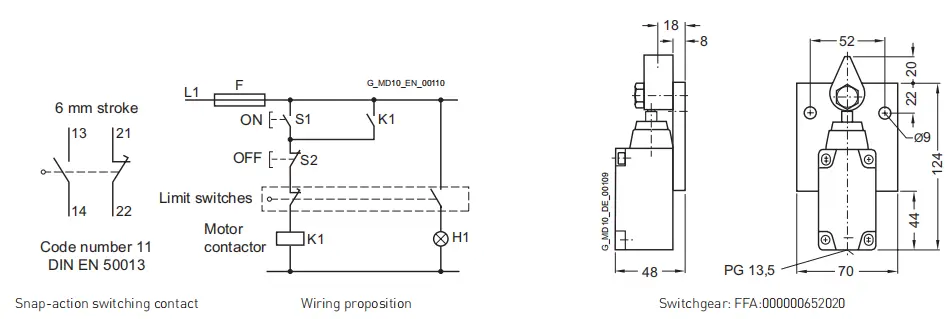
The thermal switching equipment comprises the thermal switch and the switchgear.
The switchgear comprises a limit switch with a make-andbreak contact and a swiveling cam. Limit switch and cam are mounted on a common base plate. The thermal switch is screwed into the housing in place of a screw plug. The fusible safety plug (with a higher response temperature) remains in the coupling for additional safety.
If the set temperature is exceeded, the switching pin is released from the fusible element, emerges 10 mm from the housing and actuates the switchgear while the coupling is rotating. The switchgear can cut out the drive motor and/or trigger an optical or acoustic alarm signal.
The housing of the coupling remains closed and no operating fluid will escape.
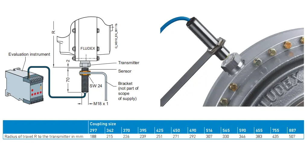
EOC system
On the EOC system the temperature-dependent magnitude of the magnetic field of the EOC transmitter is measured and used for a switching pulse. The transmitter signal is transmitted via the fixed sensor to the evaluation instrument and there compared with the set value. If the signal does not exceed the minimum value or no signal is received, the relay of the evaluation instrument switches over. This can cause a malfunction message to be sent and the motor cut out. The coupling housing remains closed.
The fusible safety plug with a higher response temperature remains in the coupling for additional safety.
The response temperature of the EOC system is 125 °C.
Function
Two opposing, radially bladed impellers are housed in a leakproof housing. The impellers are not mechanically connected to each other. Because of the axially parallel
arranged blades, the torque is transmitted independently of the direction of rotation and solely by the oil filling.
Hydrodynamic couplings have the characteristic properties of fluid flow engines. The transmissible torque depends on the density and quantity of the operating fluid and increases as the square of the drive speed and the fifth power of the profile diameter denoting the coupling size. In the driven pump impeller, mechanical energy is converted into kinetic flow energy of the operating fluid. In the turbine impeller, which is connected to the output side, flow energy is converted back to mechanical energy.
To generate the operating fluid circulation necessary for torque transmission, a difference in speed is necessary between the pump and turbine impellers. A centrifugal force pressure field is set up that is greater in the faster rotating pump impeller than in the turbine impeller.
The difference in speed, usually termed “slip”, at the continuous operating point of the coupling is between 2 % and 6 %, depending on application and coupling size.
Immediately after drive motor start-up slip is 100 %, i.e. the pump impeller is driven at the speed of the motor, but the turbine impeller remains stationary.
Slip multiplied by the transmitted power represents the power loss of the coupling, which is converted into heat inside the oil filling. The amount of heat generated must be released into the environment via the coupling housing to prevent an impermissible temperature rise. The rated coupling output is mainly determined by the power loss which can be dissipated at a still acceptable operating temperature or a reasonable set slip limit. This distinguishes the FLUDEX coupling from all positively acting coupling assembly options for which the rated coupling torque is the defining characteristic.
Depending on the FLUDEX coupling series, drive is via the inner rotor (shaft/hollow shaft with rigidly connected blade wheel) or via the bladed housing impeller (blade wheel housing). The driving impeller is the pump impeller, and the driven impeller is the turbine impeller.
A low-viscosity mineral oil VG 22/VG 32, which also serves to lubricate the bearings, is used as fluid. In special types water, a water emulsion or low-flammability fluid may be used as a non-combustible fluid.