 SIEMENS Helical Gearmotor Low Voltage
 SIEMENS Bevel Helical Gearmotor
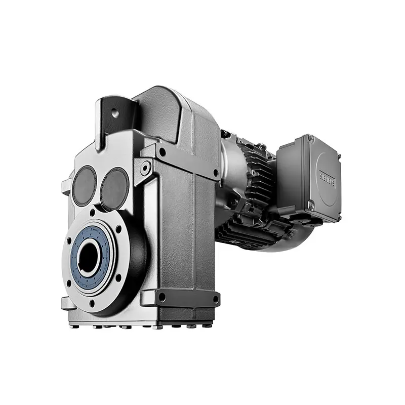 SIEMENS Parallel Shaft Gearmotor
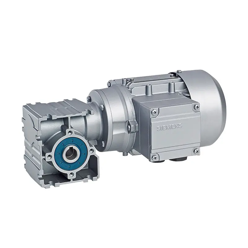 SIEMENS Worm Gearmotor Low Voltage
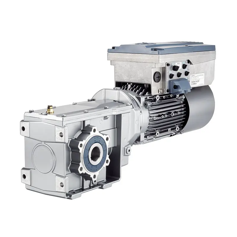 SIEMENS With Servo Motor Gearmotor
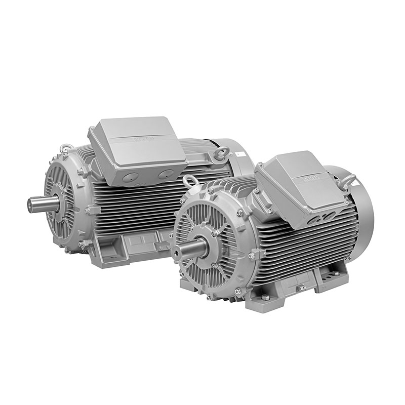 SIEMENS Low Voltage Motor Low Voltage
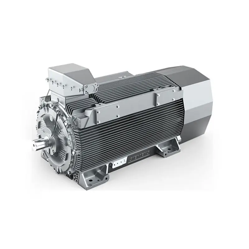 SIEMENS High Voltage Motor Low Voltage
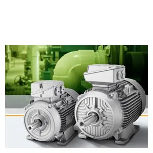 SIEMENS Marine Motor Low Voltage
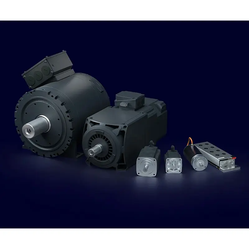 SIEMENS Servo Motor Low Voltage
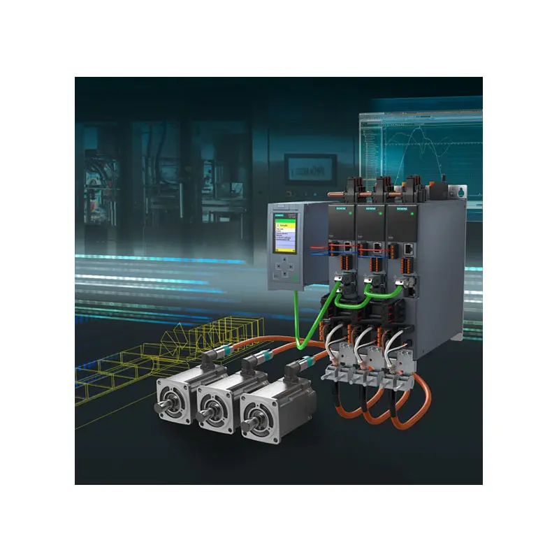 SIEMENS SINAMICS S210 Low Voltage
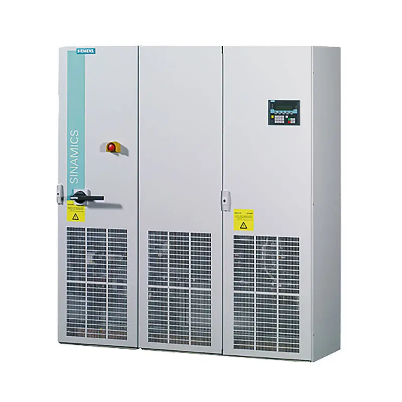 SIEMENS SINAMICS S150 Low Voltage
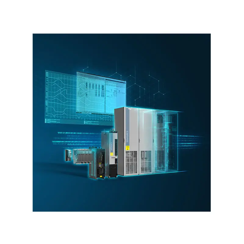 SIEMENS SINAMICS S120 Low Voltage
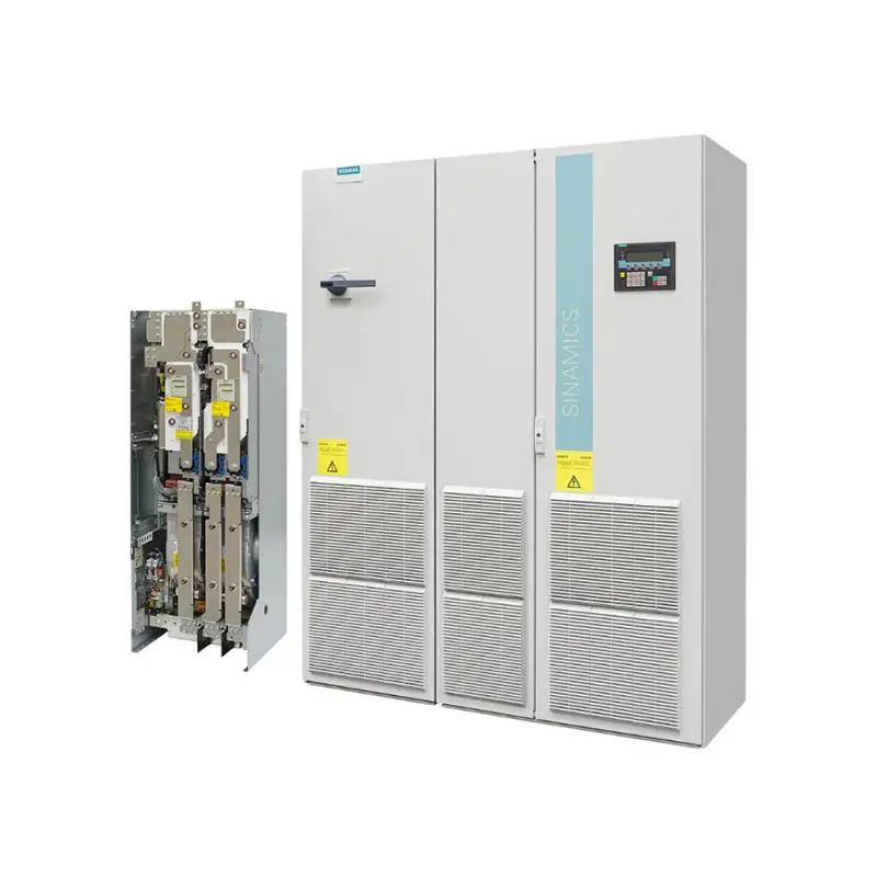 SIEMENS SINAMICS G130/G150
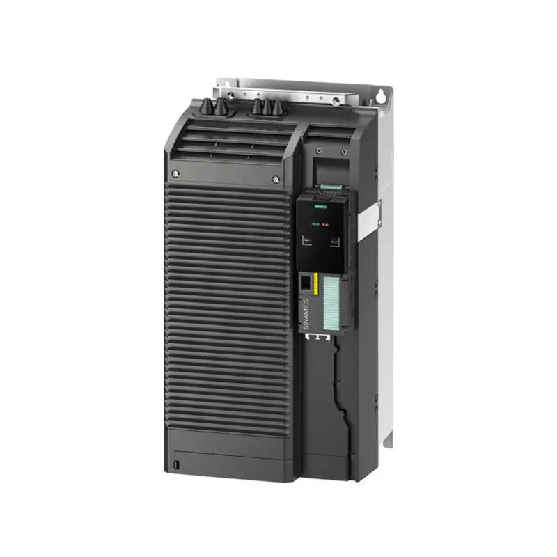 SIEMENS SINAMICS G120 Low Voltage
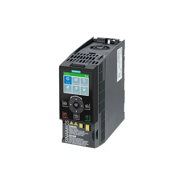 SIEMENS SINAMICS G120C Low Voltage
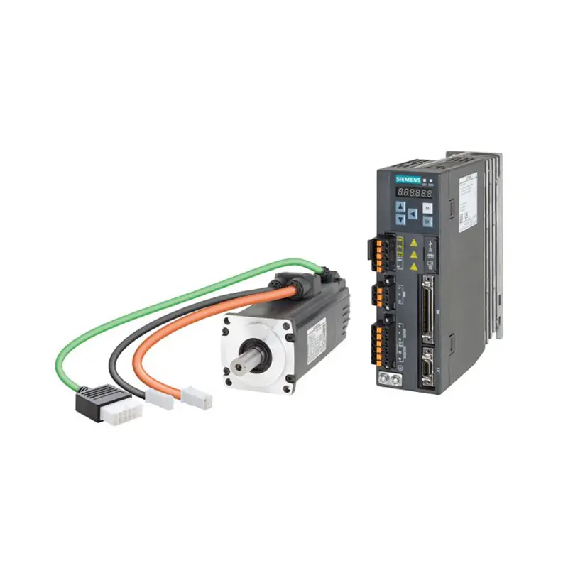 SIEMENS SINAMICS V90
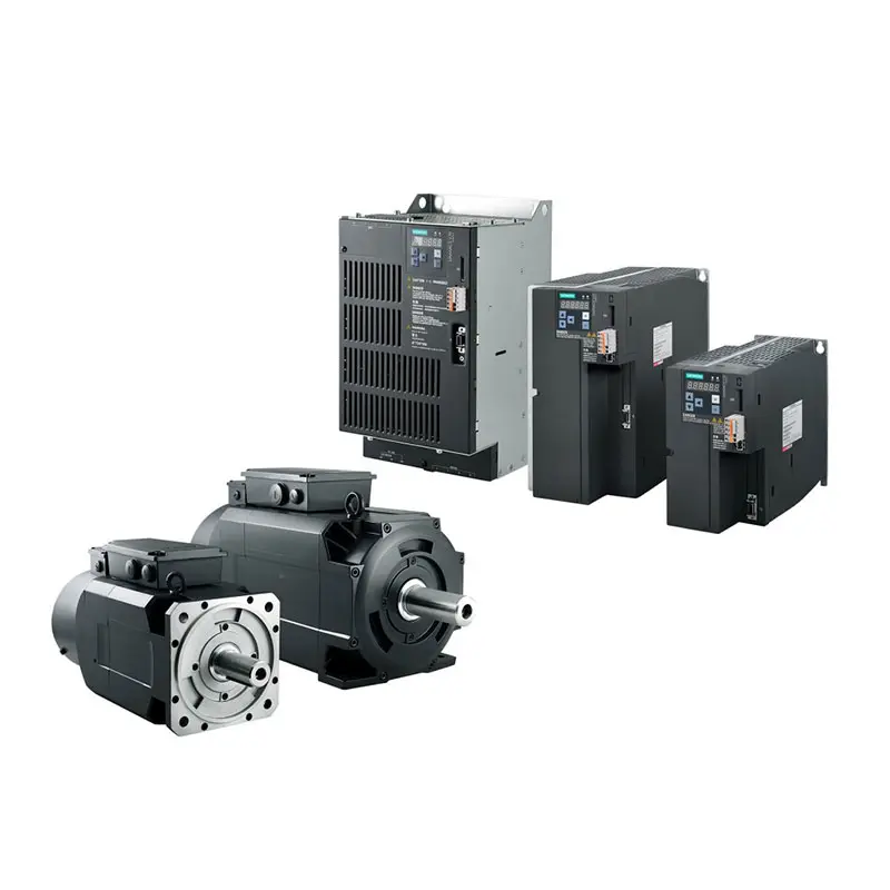 SIEMENS SINAMICS V70 Low Voltage
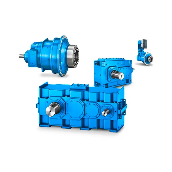 FLENDER Gear Unit
 FLENDER Helical Gear Unit
 Flender gear units for lifting and luffing gears
 FLENDER Gear Unit gearunit gearbox
 Optimal Drive Solution For Maximum Performance
 Strongly operating against biodegradable constituents
 SINGLE SCREW Special industry dedicated gearunit gearbox
 Playmaker In The Premium League
 Conveyor belts gearunit gearbox
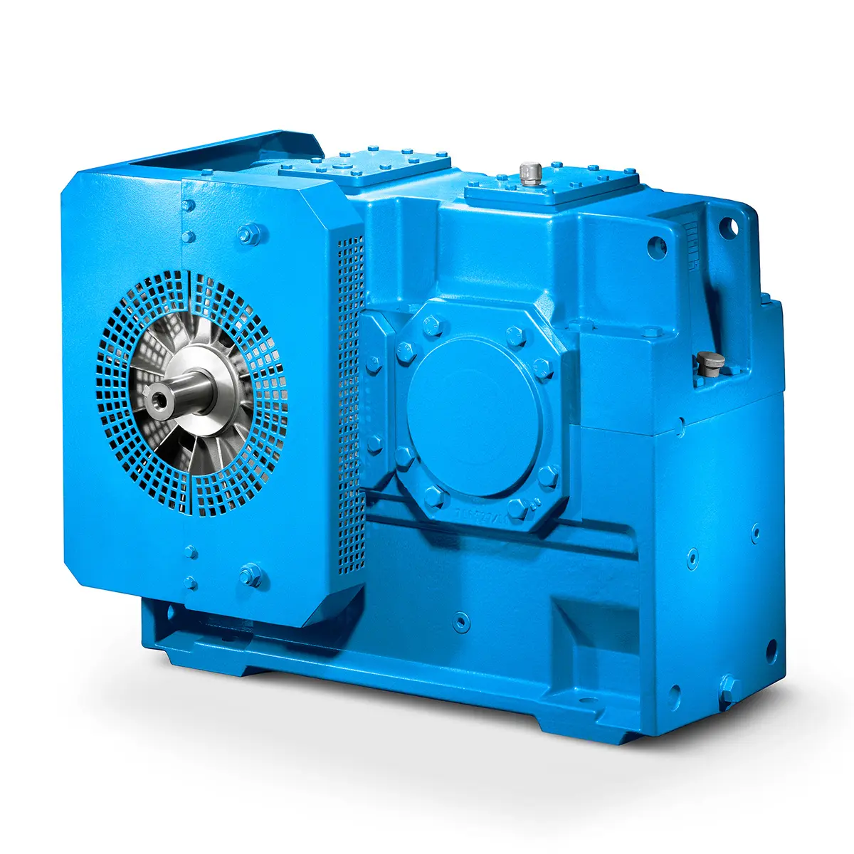 Paper And Pulp Preparation Sections
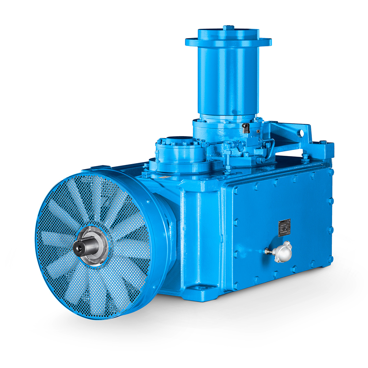 Operational Reliability Even In Case Of The Highest Ventilation Forces
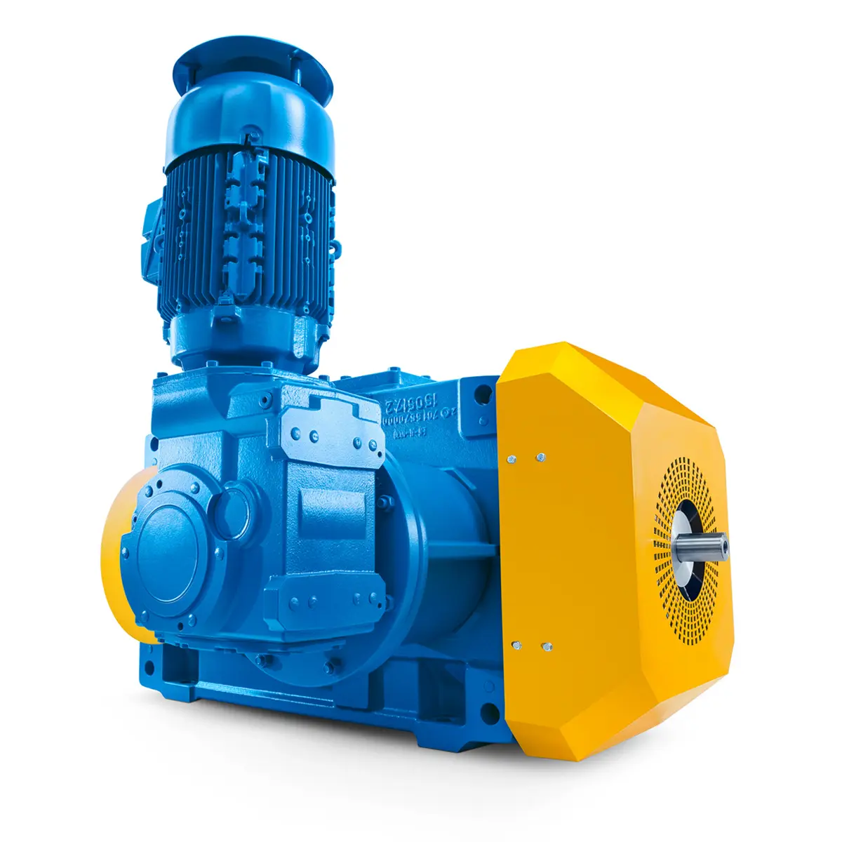 Reliable Gear Units For High Performance Vertical Conveyors 59/200
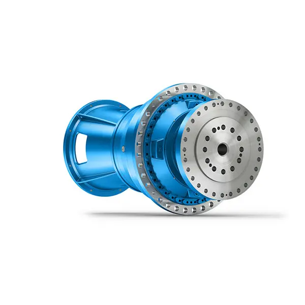 Maximum power density – PLANUREX 3 L individual drives for your sugar cane mill
 The proven all rounder gearunit gearbox
 Stirs and stirs and stirs gearunit gearbox
 Flexibility on Board gearunit gearbox
 The right gearbox for all Multi-Engine Ships
 Reliable Power Generation on board
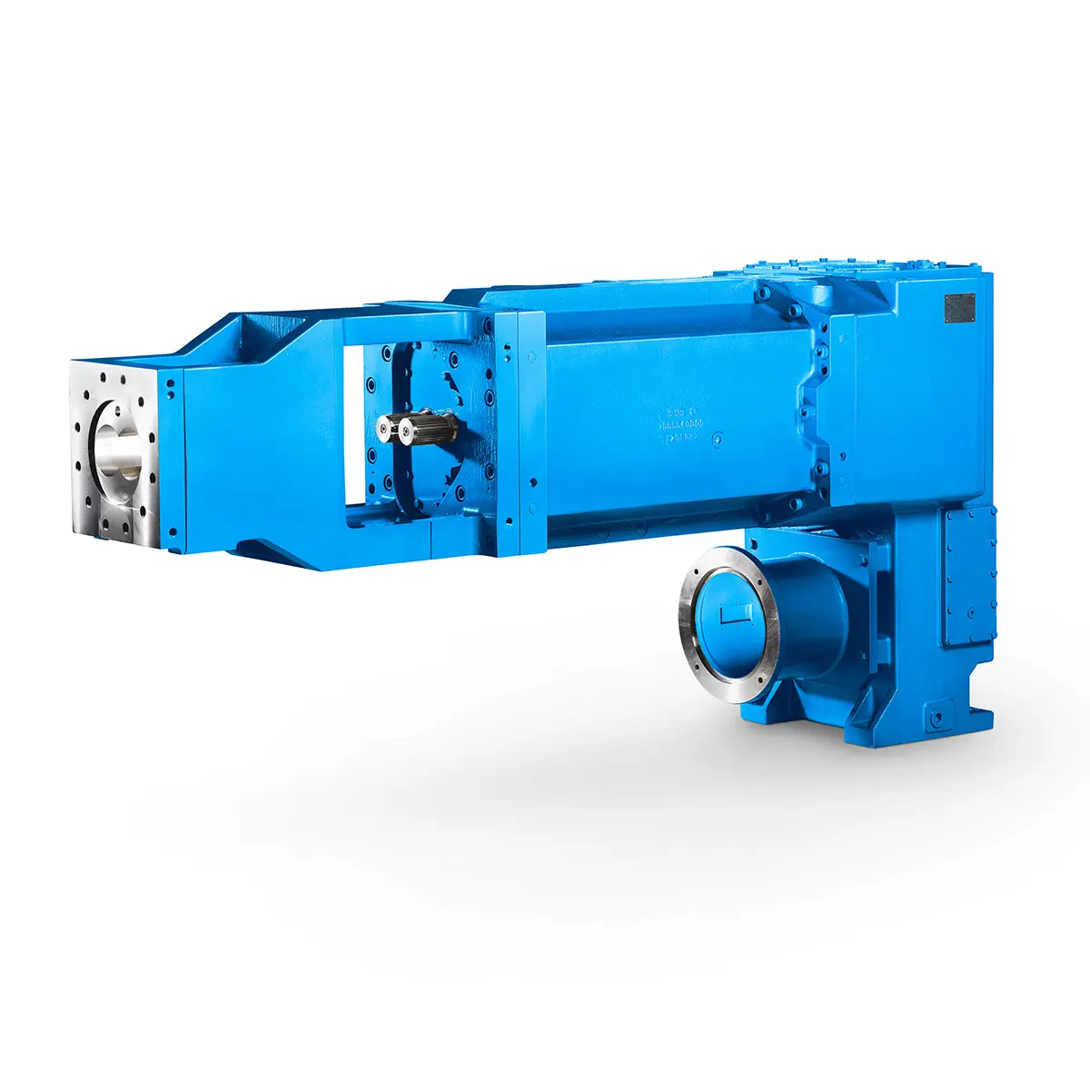 Maximum performance level, fast deliverable
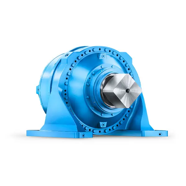 Efficient and compact – FLENDER Gear Units for Sugar Mills
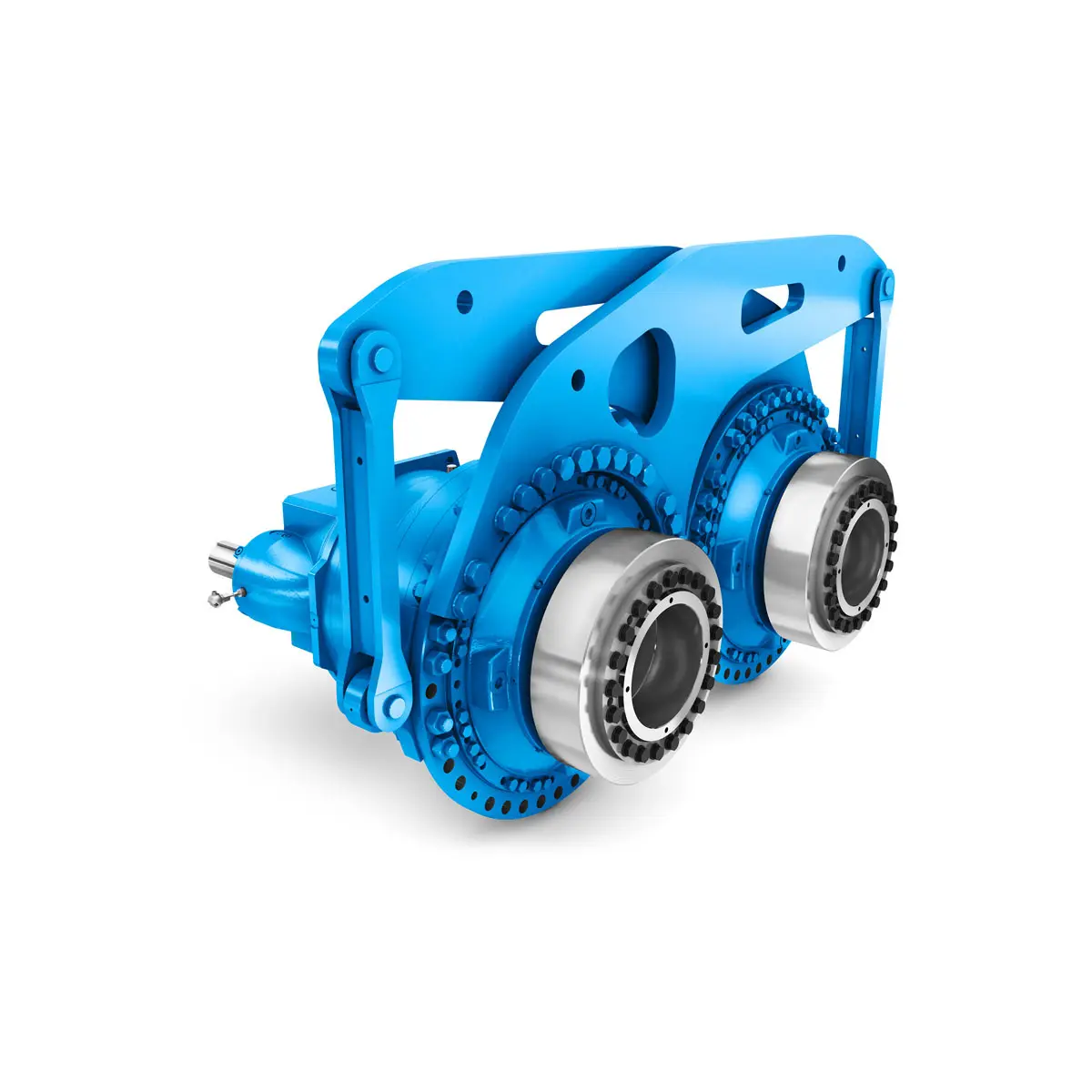 Extremely strong. Extremely compact. Extremely stressable.
 FLENDER Coupling
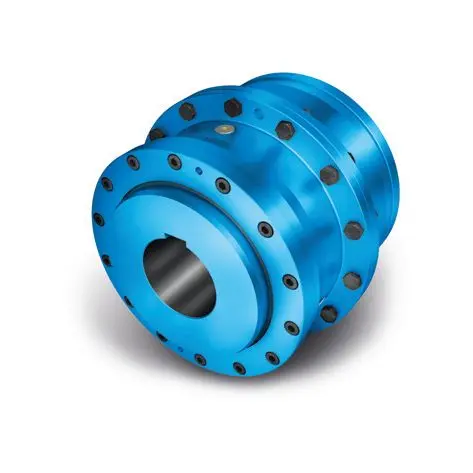 ZAPEX ZW Torsionally Rigid Gear Coupling
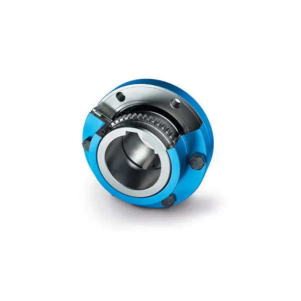 ZAPEX ZN Torsionally Rigid Gear Coupling
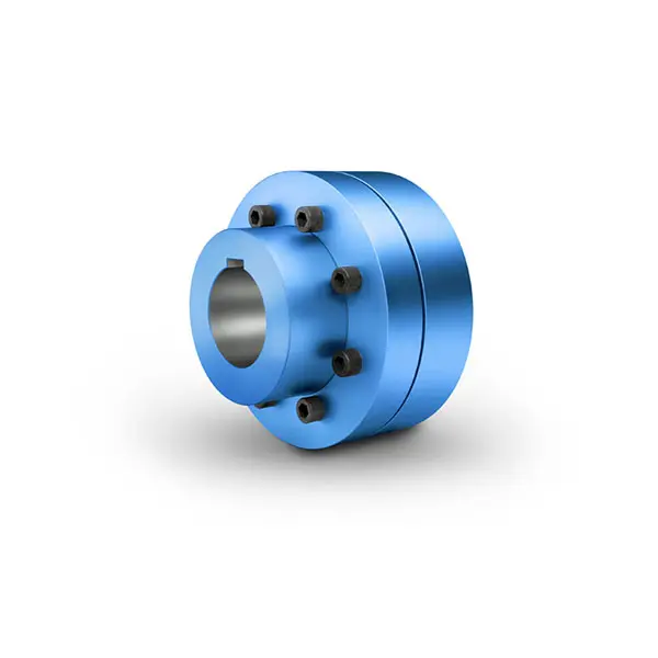 N-EUPEX Flexible high performance Coupling
 N-ARPEX Torsionally Rigid All-Steel Coupling
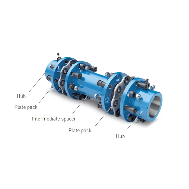 ARPEX Torsionally Rigid All-Steel Coupling Spare and Parts
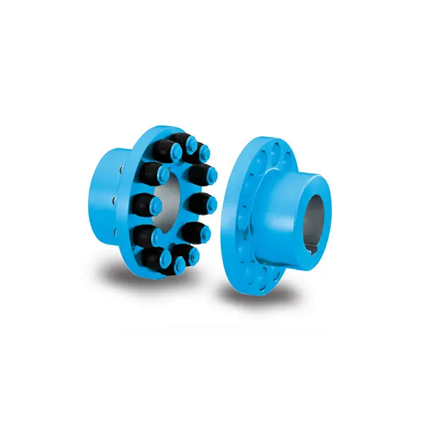 RUPEX Flexible high performance Coupling
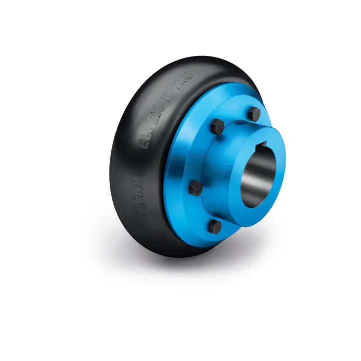 ELPEX B Highly Flexible Coupling
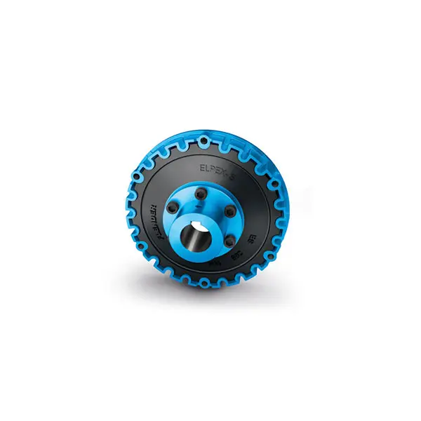 ELPEX S Highly Flexible Coupling high performance
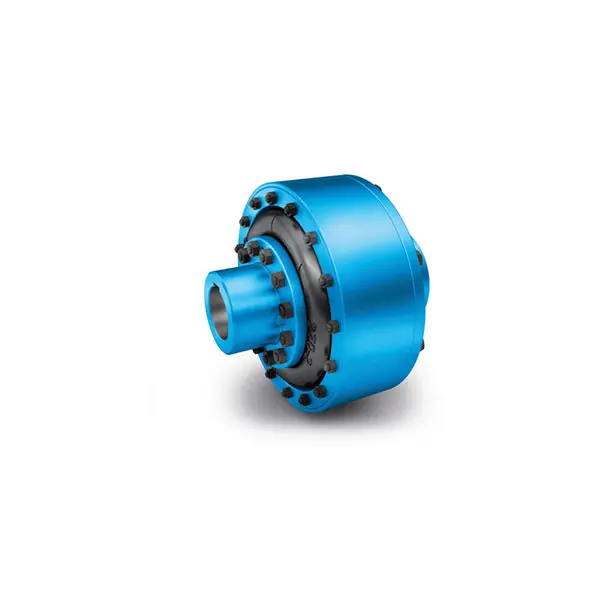 ELPEX Highly Flexible Coupling high performance
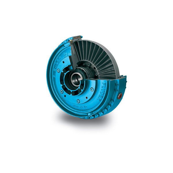 FLUDEX Fluid Coupling high performance
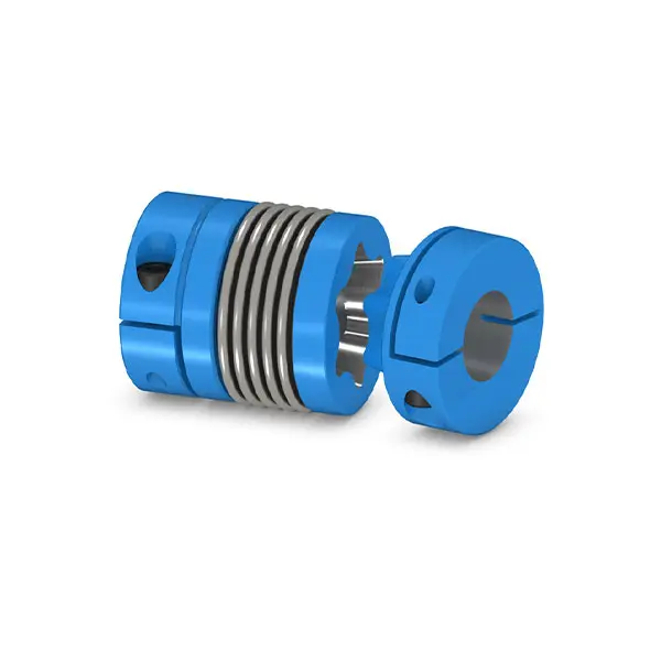 SIPEX Backlash free Coupling high performance
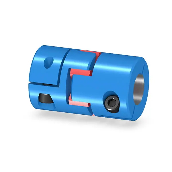 BIPEX S Backlash free Coupling high performance
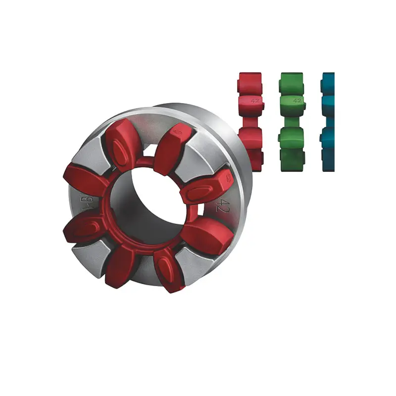 FLENDER Coupling Spare Parts high performance
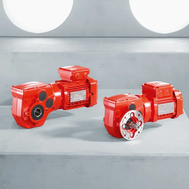 SEW Gearmotor
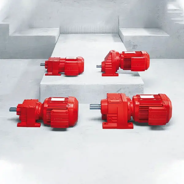 R Series Helical Gearmotor low voltage
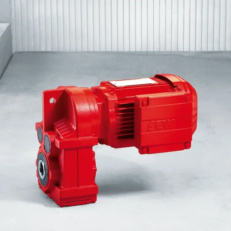 F Series Parallel Shaft Gearmotor low voltage
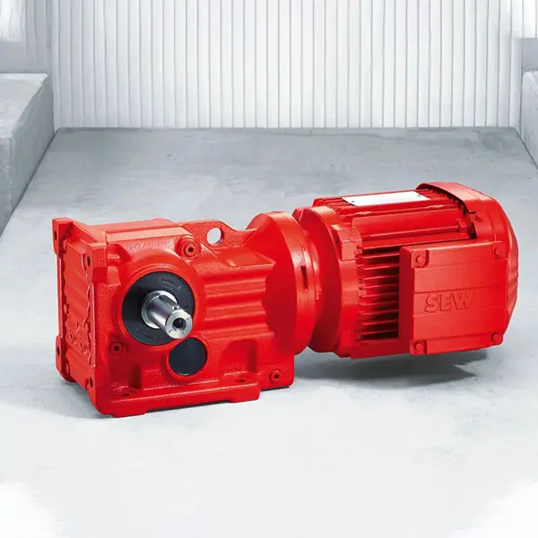 K Series Helical Bevel Gearmotor low voltage
 S Series Helical Worm Gearmotor low voltage
 W Series SPIROPLAN® Right Angle Gearmotor
FLENDER Coupling
- SIEMENS Gearmotor
- NORD Industrial Gear Unit
- LENZE Gearmotor
- NORD Gearmotor
- SEW Planetary Gear Unit
- SEW Industrial Gear Unit
- SEW Gearmotor
- BONFIGLIOLI Precision Planetary Gearbox and Gearmotor
- BONFIGLIOLI Inverters and Servo drives
- BONFIGLIOLI Industrial Gear Unit
- BONFIGLIOLI Gearmotor
- FLENDER Coupling
- FLENDER Gear Unit
01

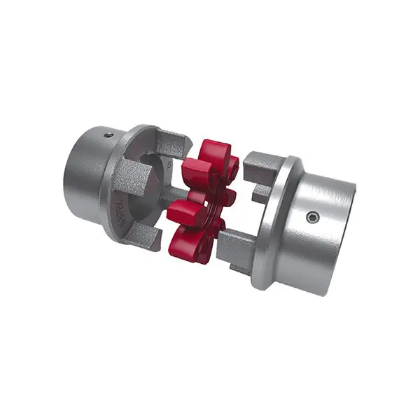
N BIPEX Flexible high performance coupling
Benefits
N-BIPEX couplings are suitable for horizontal, vertical and freely selectable mounting positions. They are able to absorb axial, radial and angular misalignment.
N-BIPEX couplings consist of two identical hub parts which can be arranged as required on the shaft extensions to be connected. N-BIPEX couplings transmit the
torque positively and are thus fail-safe. The curved design of the cast cams ensures that the N-BIPEX couplings have a perfect pressure distribution and this increases the elastomer lifetime.
The flexible cam rings responsible for torque transmission and misalignment compensation are available in different Shore hardnesses. As a result of the good damping capability and by selecting the suitable stiffness, torque shock loads can thus be absorbed and the torsional vibration behavior of the drive can be positively influenced.
Different cam ring versions and ready-to-install hub parts are available from stock.
Application
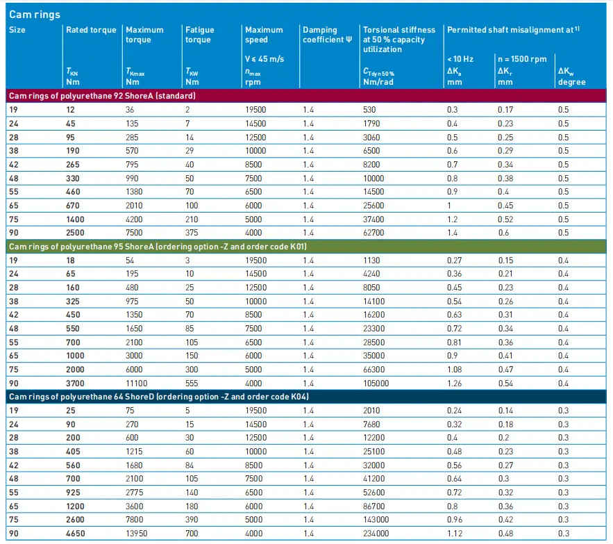
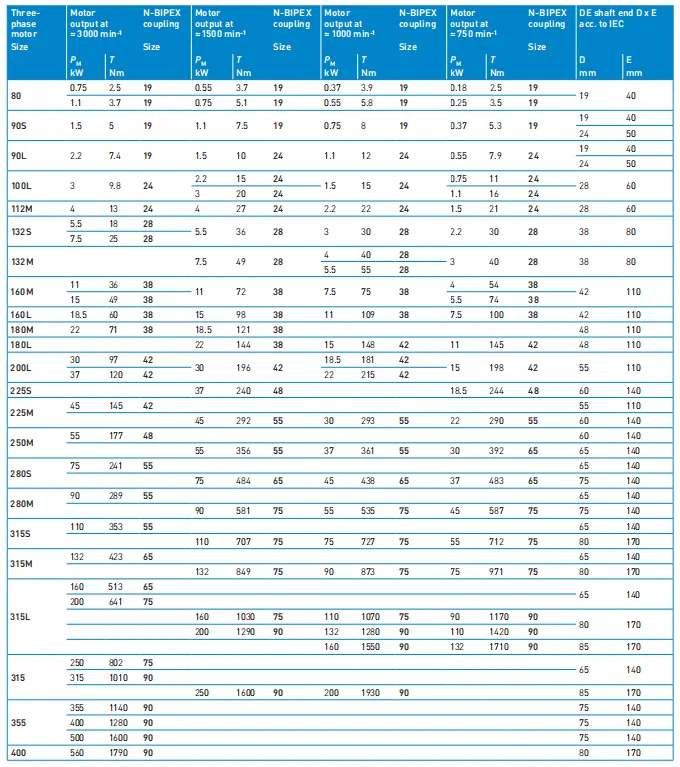
The N-BIPEX coupling is available as a catalog standard in 10 sizes with rated torques of between 12 Nm and 4650 Nm and is made of high-grade spheroidal graphite cast iron.
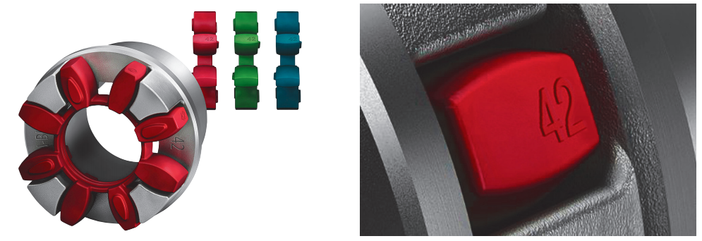
The extremely high-performance cam ring materials are available from stock in three different Shore hardnesses with the following colors:
• 92 ShoreA – red
• 95 ShoreA – green
• 64 ShoreD – blue
An additional size marking has been provided on the outer surface of the cam ring to be able to determine the size of the N-BIPEX even when it is in the assembled state without having to use any additional aids.
The coupling is suitable for use at ambient temperatures between -50 °C and +100 °C without any restrictions on the rated torque as a result of temperature factors.
Function
The torque is transmitted to the hub at the drive end via the shaft-hub connection, which is mostly designed as a keyway connection, and is transmitted to the hub on the
output side via the cam ring. This hub then further transmits the torque to the driven machine or a gear unit placed in between.
The special cam ring design helps to keep the compression-loaded cam ring elements in their defined position under all operating conditions and to keep them evenly loaded. This results in a long lifetime of the flexible elements.
A long lifetime is also guaranteed by the hub parts which ensure maximum operational reliability even under harsh operating conditions.
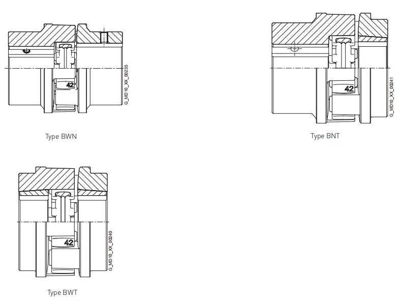
Design and configurations
The N-BIPEX coupling of type BWN comprises two identical hub parts connected by a cam ring of elastomer material.
The hubs are connected to the respective shafts via finished bores with parallel keyway connection or Taper clamping bushes. N-BIPEX couplings are positive-locking and torsionally flexible thanks to the thermoplastic polyurethane cam ring.
Hubs:
• Steel 1)
Cam ring:
• TPU 92 ShoreA
-50 °C to +100 °C/120 °C without /with restrictions
• TPU 95 ShoreA
-50 °C to +100 °C/120 °C without /with restrictions
• TPU 64 ShoreD
-50 °C to +100 °C/120 °C without /with restrictions
The coupling comprises the following:
• Cam ring
• 2 hub parts with identical cams
The hub parts are designed with a bore and keyway to DIN 6885-1 or with a taper bore for mounting a Taper clamping bush.
Fitting the clamping bush connects the hub firmly to the machine shaft.
In the case of part 4 the Taper clamping bush is inserted from the machine housing side. If there is insufficient space, the Taper clamping bush cannot be fitted from this side. Besides space for fitting the Taper clamping bush, space for the fitting tool (offset screwdriver) must be taken into consideration. In the case of part 3, the Taper clamping bush is screwed in from the shaft end face side. The hub must be fitted before the machines to be connected are pushed together.
Design and configurations
Technical specifications