 SIEMENS Helical Gearmotor Low Voltage
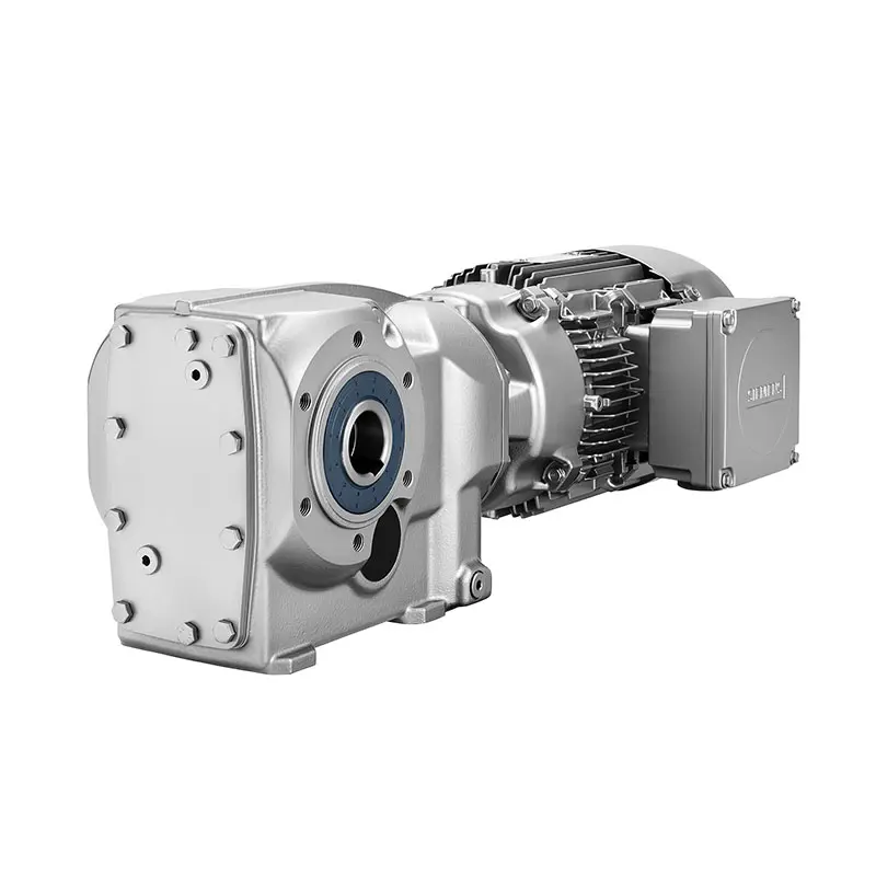 SIEMENS Bevel Helical Gearmotor
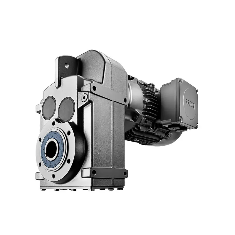 SIEMENS Parallel Shaft Gearmotor
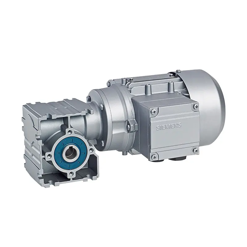 SIEMENS Worm Gearmotor Low Voltage
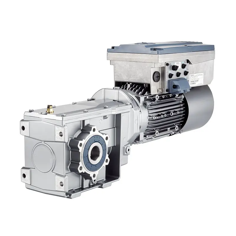 SIEMENS With Servo Motor Gearmotor
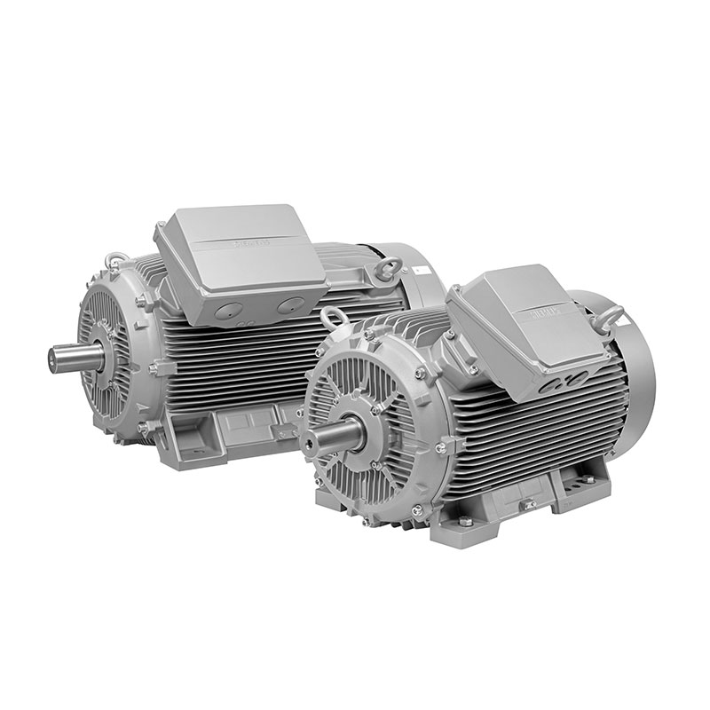 SIEMENS Low Voltage Motor Low Voltage
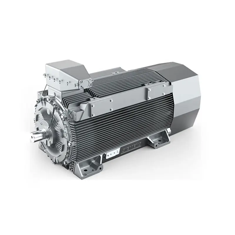 SIEMENS High Voltage Motor Low Voltage
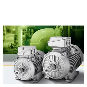 SIEMENS Marine Motor Low Voltage
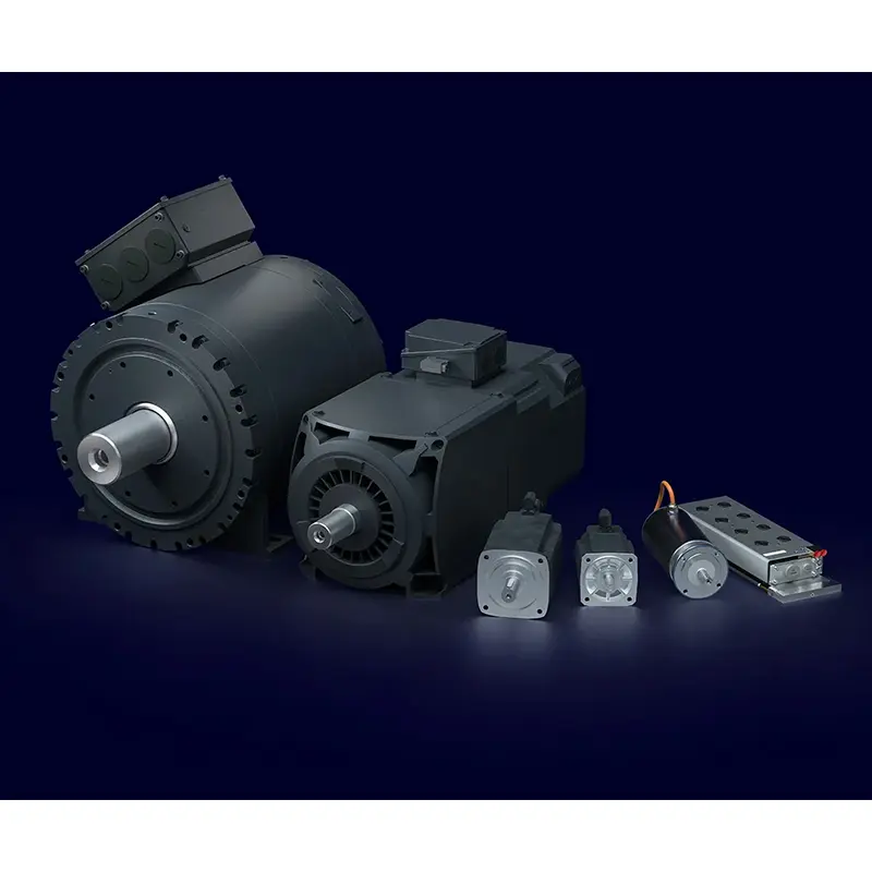 SIEMENS Servo Motor Low Voltage
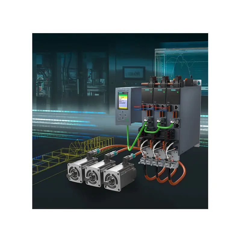 SIEMENS SINAMICS S210 Low Voltage
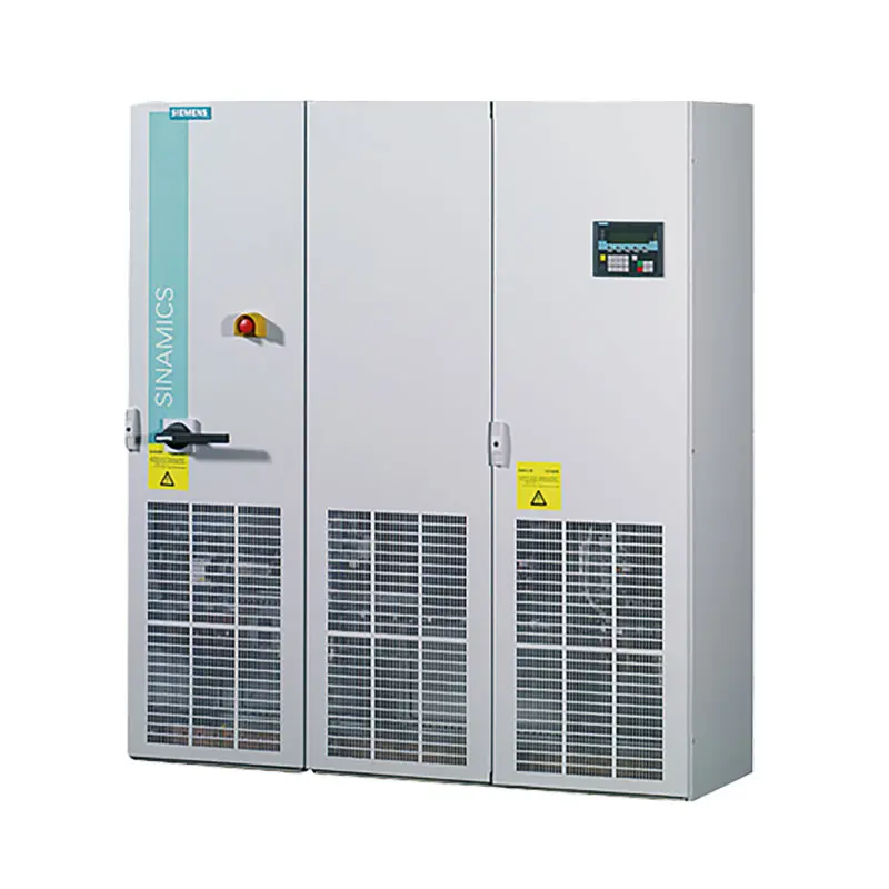 SIEMENS SINAMICS S150 Low Voltage
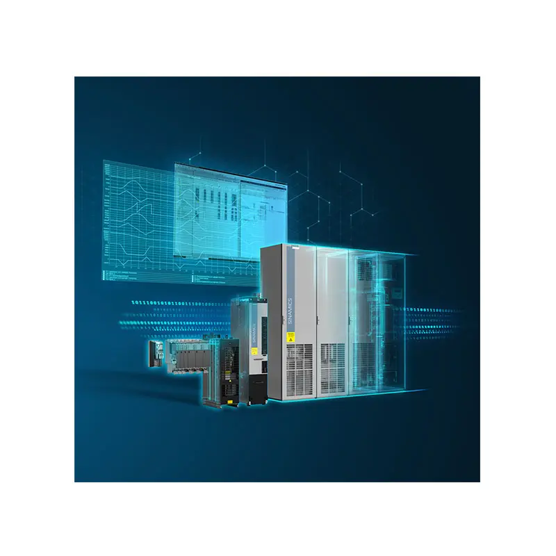 SIEMENS SINAMICS S120 Low Voltage
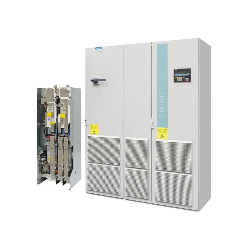 SIEMENS SINAMICS G130/G150
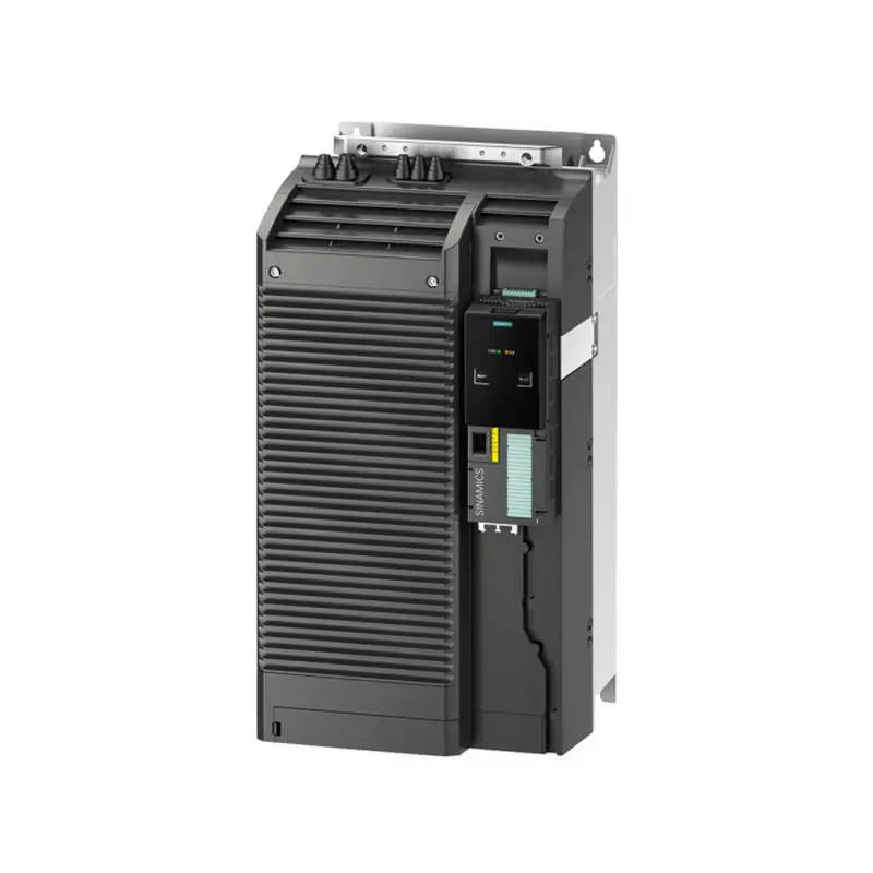 SIEMENS SINAMICS G120 Low Voltage
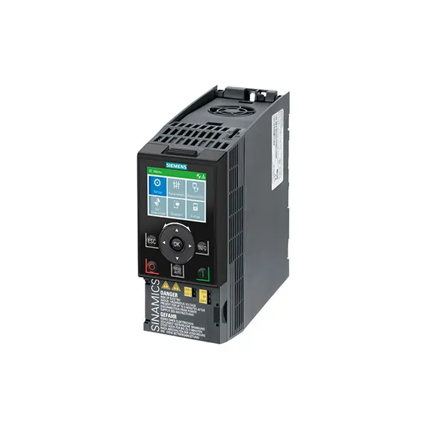 SIEMENS SINAMICS G120C Low Voltage
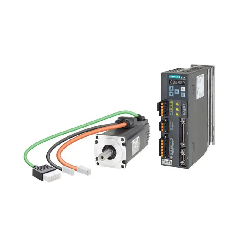 SIEMENS SINAMICS V90
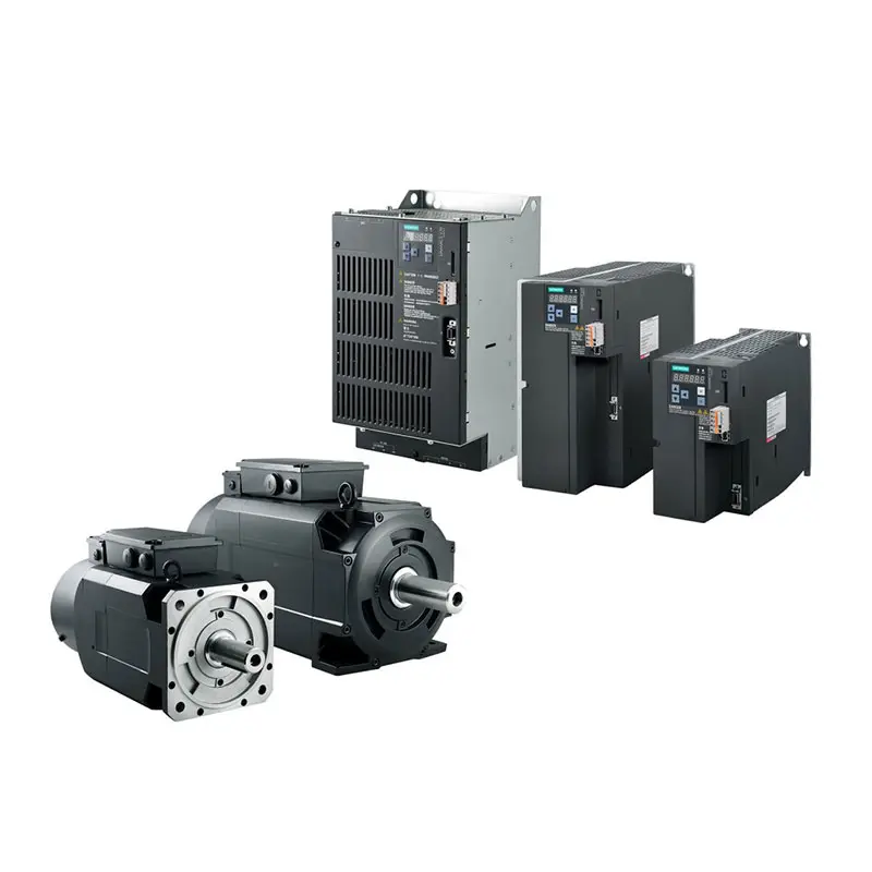 SIEMENS SINAMICS V70 Low Voltage
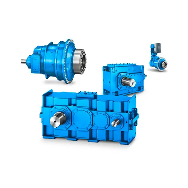 FLENDER Gear Unit
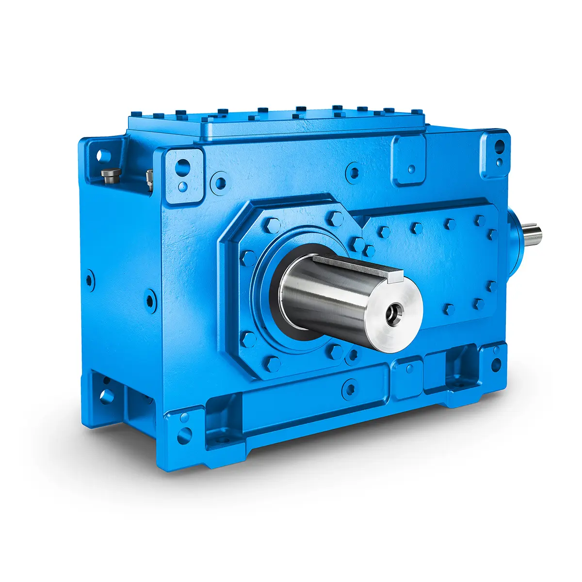 FLENDER Helical Gear Unit
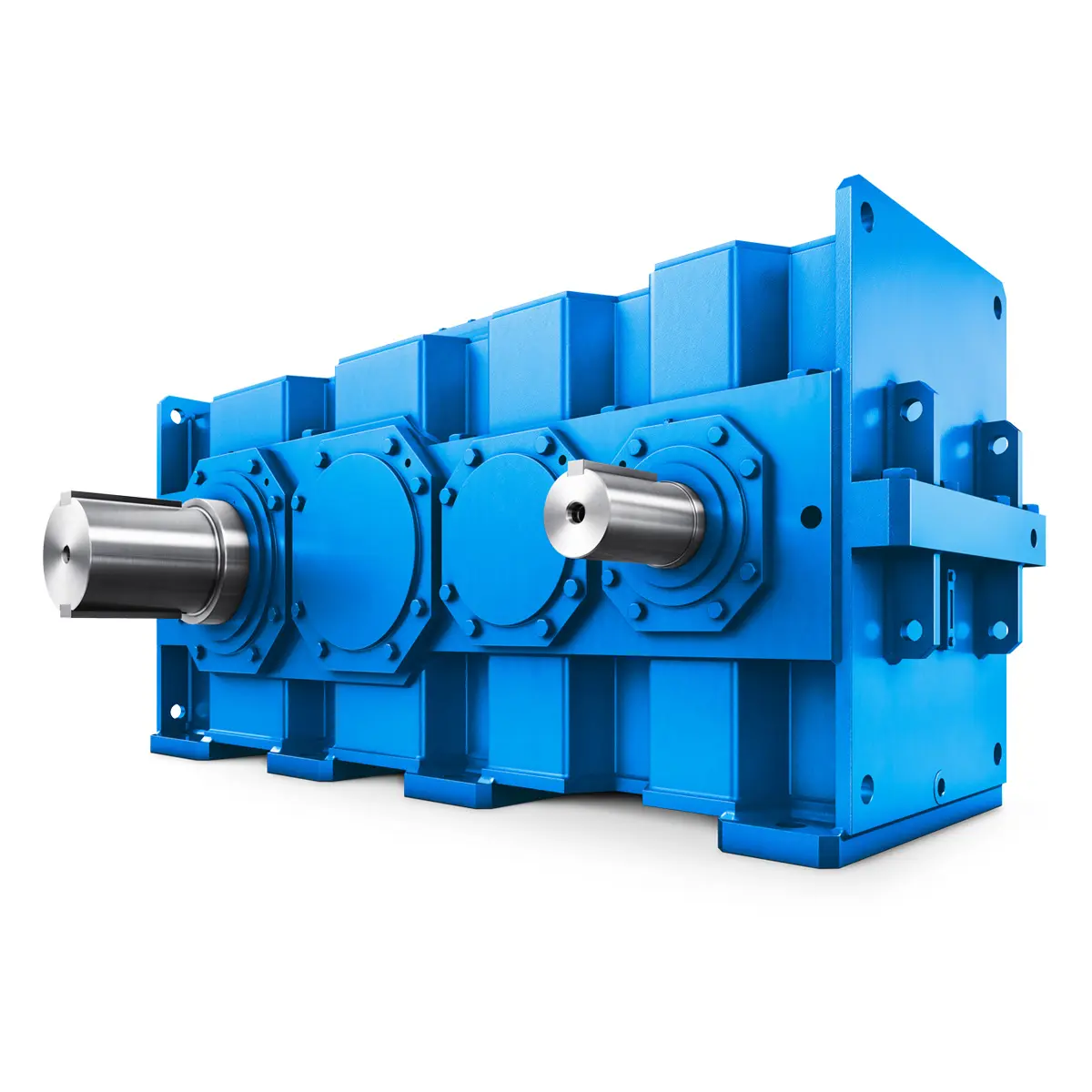 Flender gear units for lifting and luffing gears
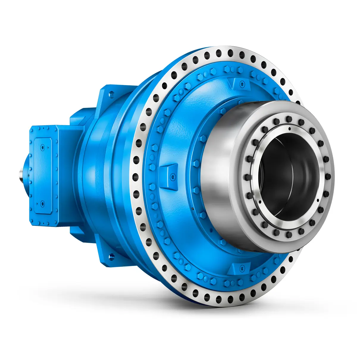 FLENDER Gear Unit gearunit gearbox
 Optimal Drive Solution For Maximum Performance
 Strongly operating against biodegradable constituents
 SINGLE SCREW Special industry dedicated gearunit gearbox
 Playmaker In The Premium League
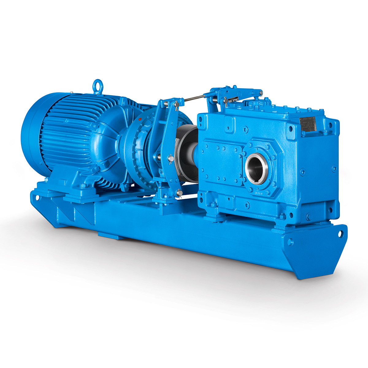 Conveyor belts gearunit gearbox
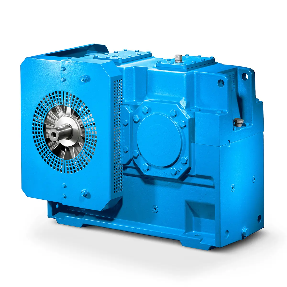 Paper And Pulp Preparation Sections
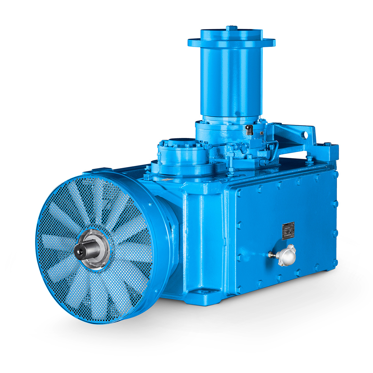 Operational Reliability Even In Case Of The Highest Ventilation Forces
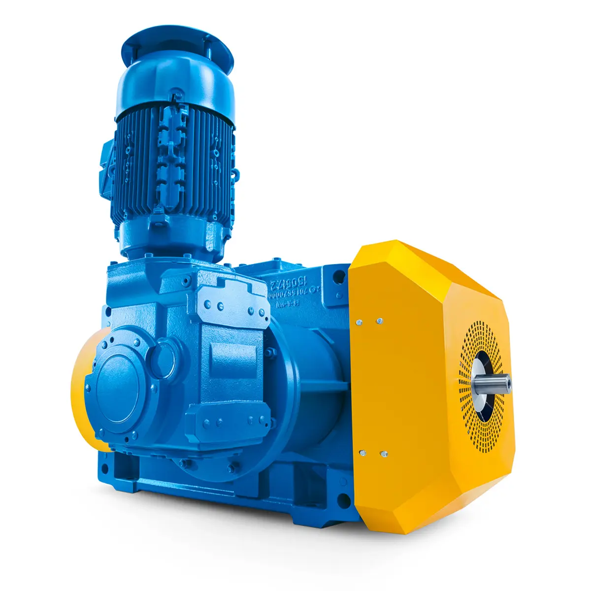 Reliable Gear Units For High Performance Vertical Conveyors 59/200
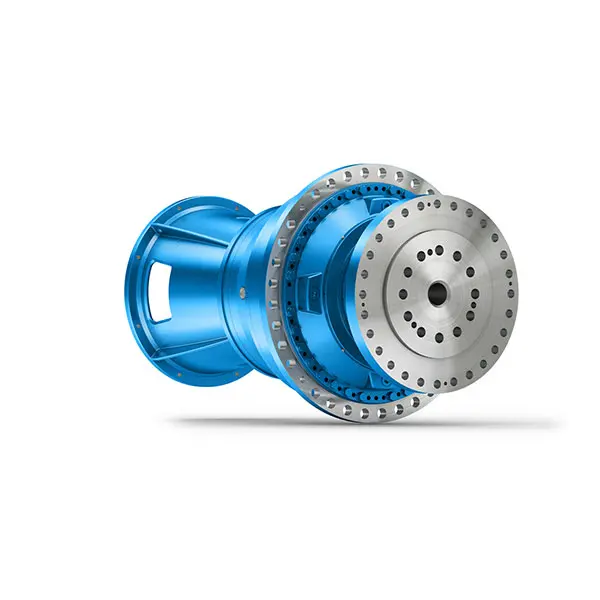 Maximum power density – PLANUREX 3 L individual drives for your sugar cane mill
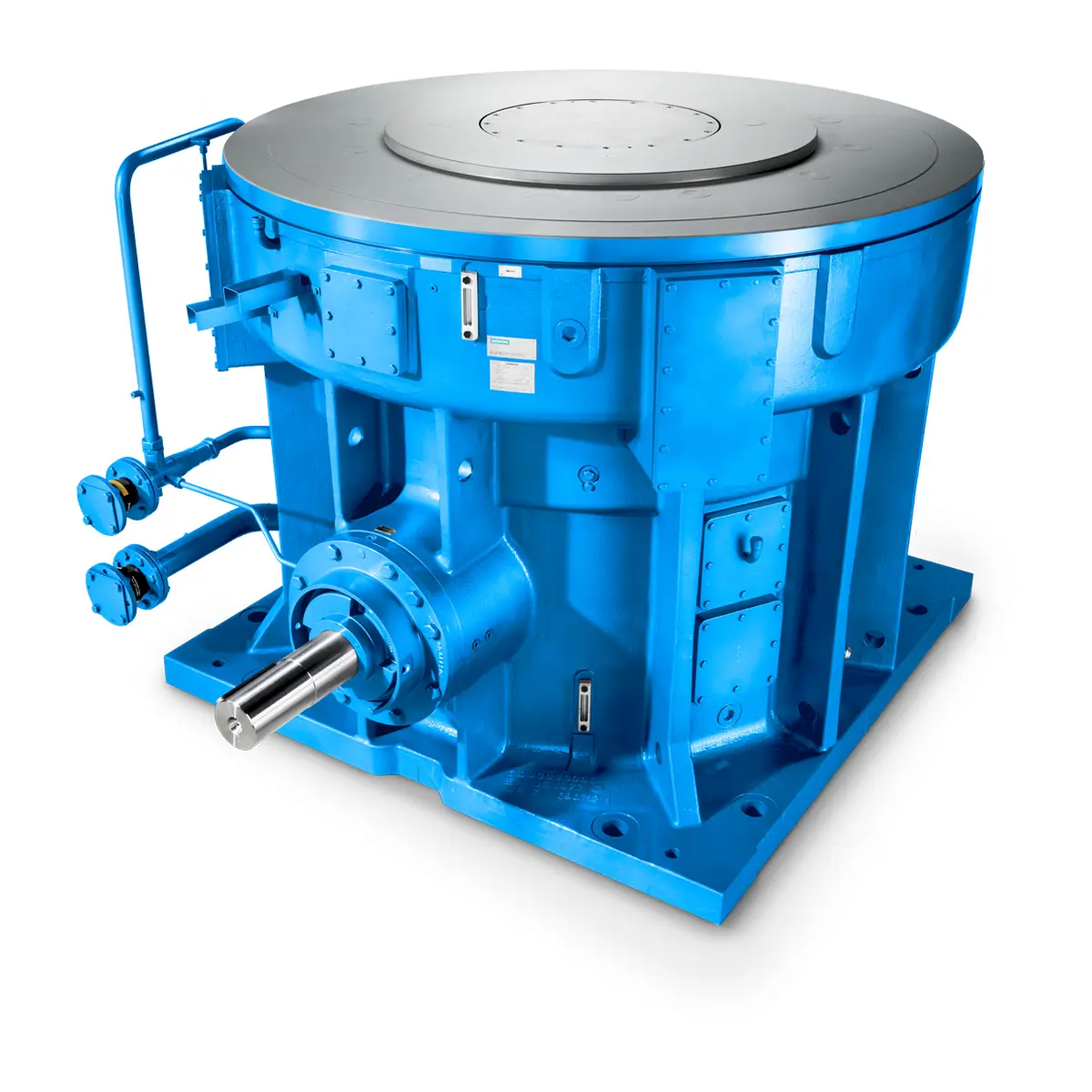 The proven all rounder gearunit gearbox
 Stirs and stirs and stirs gearunit gearbox
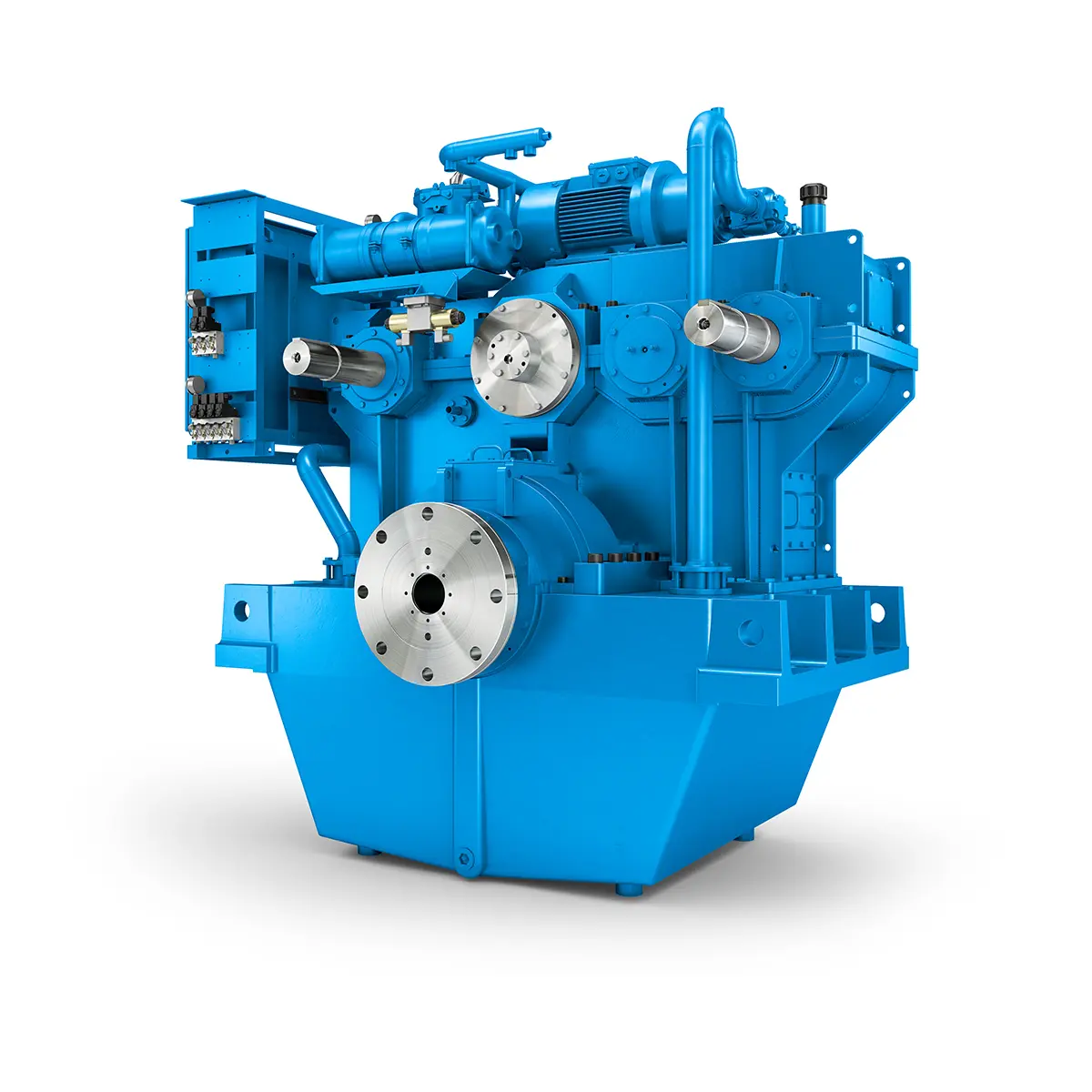 Flexibility on Board gearunit gearbox
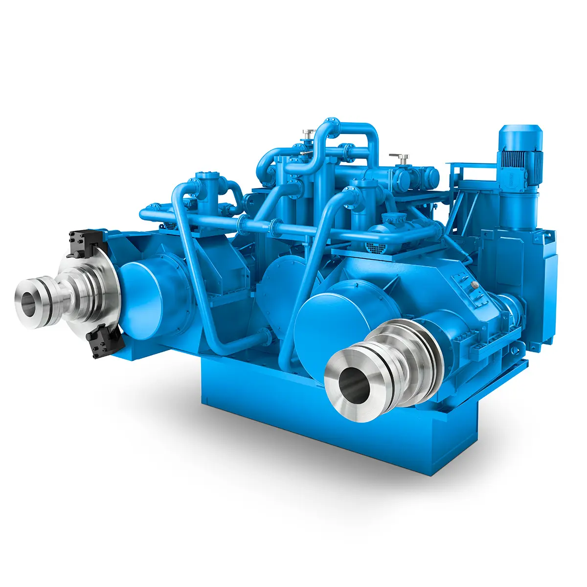 The right gearbox for all Multi-Engine Ships
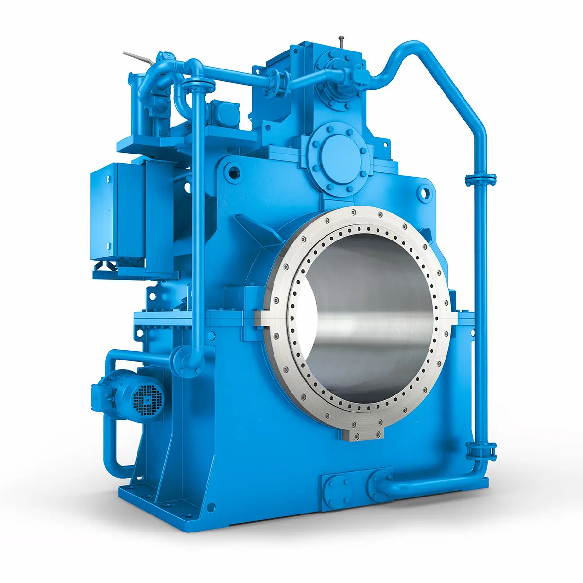 Reliable Power Generation on board
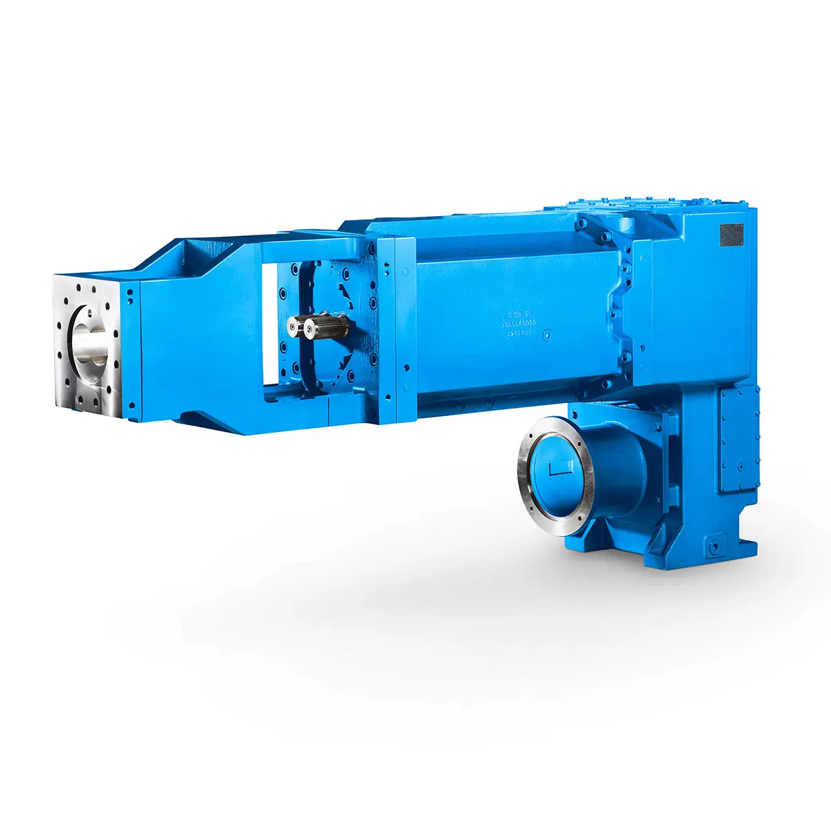 Maximum performance level, fast deliverable
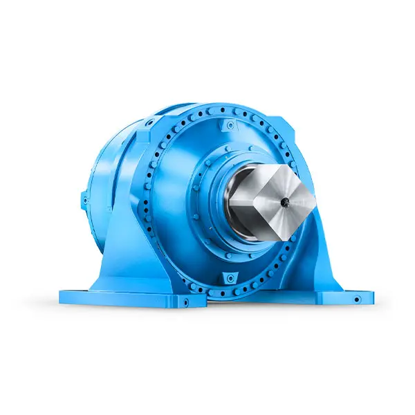 Efficient and compact – FLENDER Gear Units for Sugar Mills
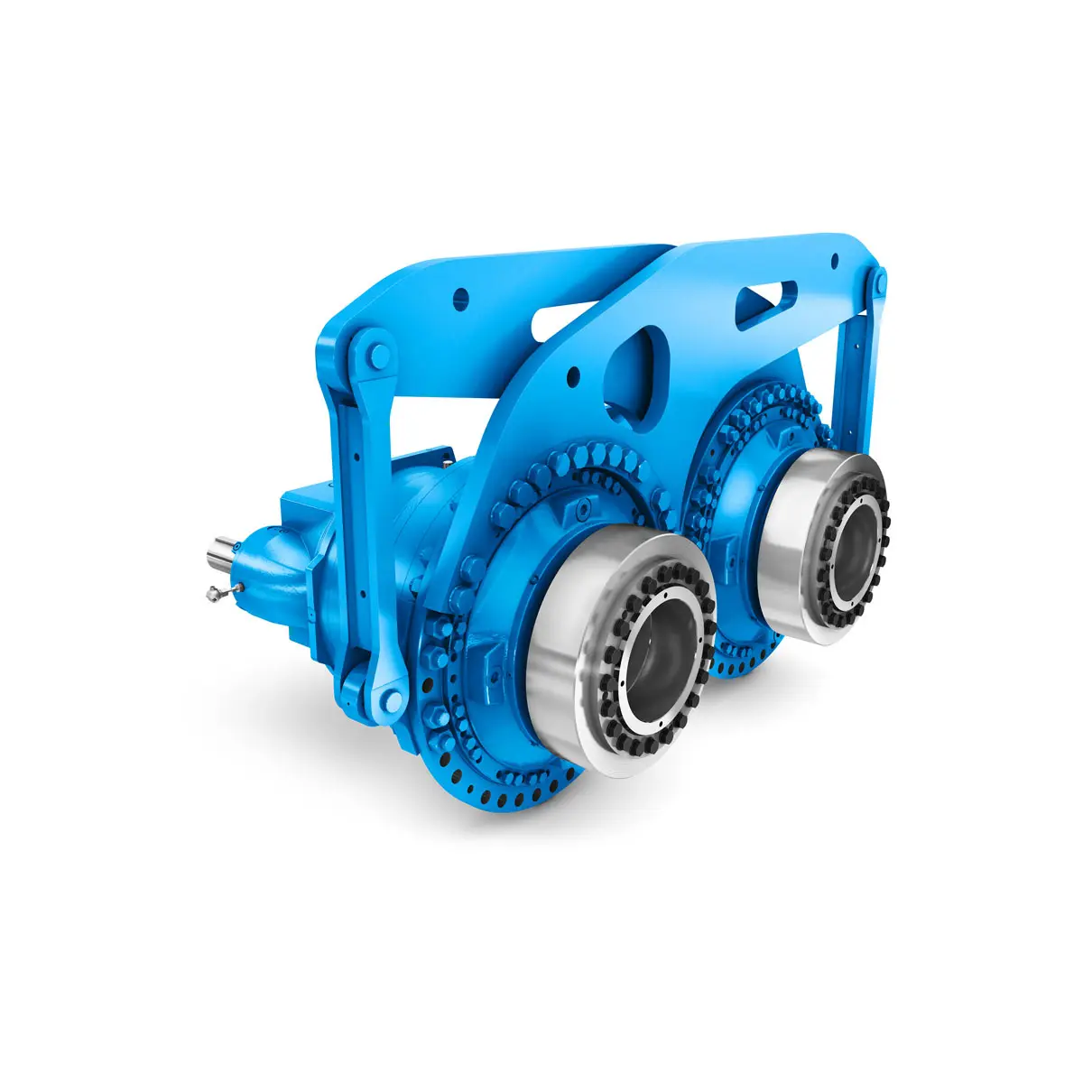 Extremely strong. Extremely compact. Extremely stressable.
 FLENDER Coupling
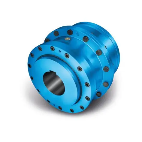 ZAPEX ZW Torsionally Rigid Gear Coupling
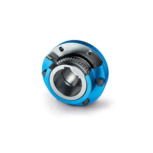 ZAPEX ZN Torsionally Rigid Gear Coupling
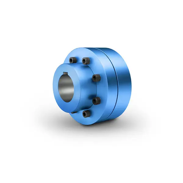 N-EUPEX Flexible high performance Coupling
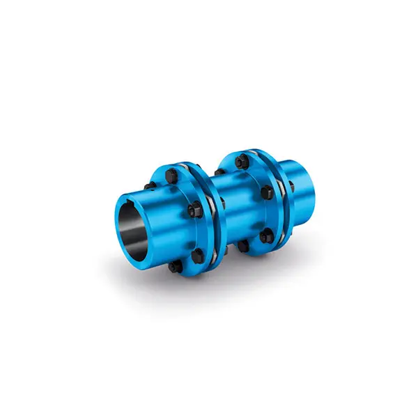 N-ARPEX Torsionally Rigid All-Steel Coupling
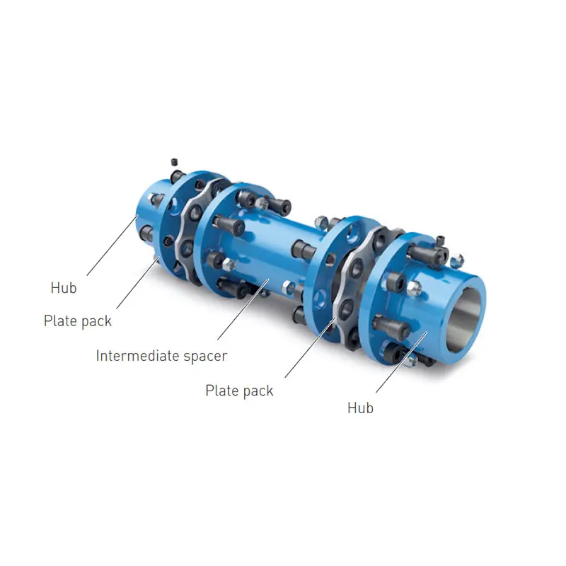 ARPEX Torsionally Rigid All-Steel Coupling Spare and Parts
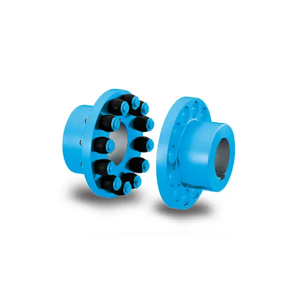 RUPEX Flexible high performance Coupling
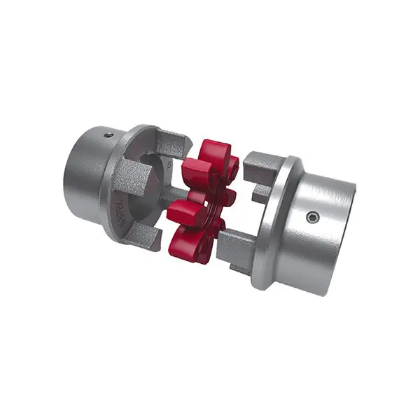 N BIPEX Flexible high performance coupling
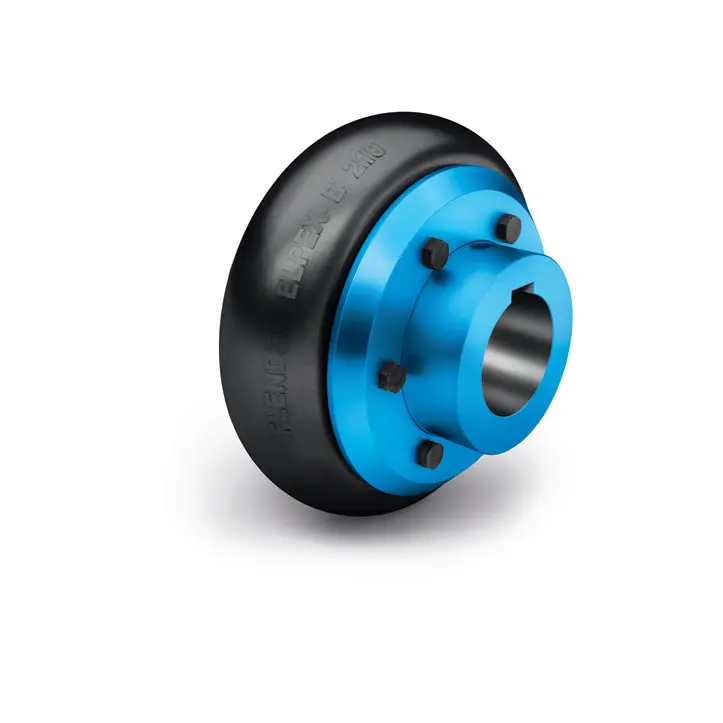 ELPEX B Highly Flexible Coupling
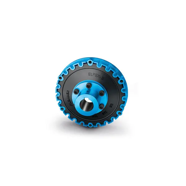 ELPEX S Highly Flexible Coupling high performance
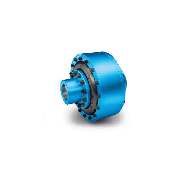 ELPEX Highly Flexible Coupling high performance
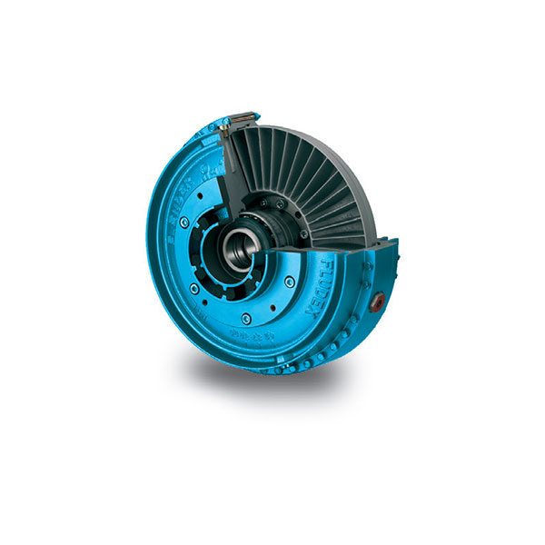 FLUDEX Fluid Coupling high performance
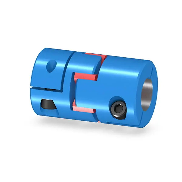 BIPEX S Backlash free Coupling high performance
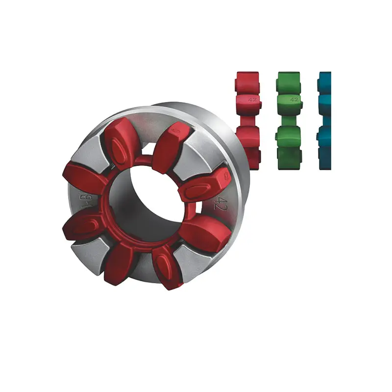 FLENDER Coupling Spare Parts high performance
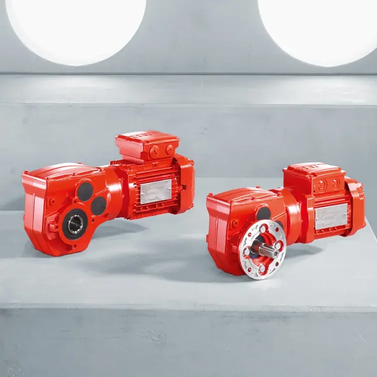 SEW Gearmotor
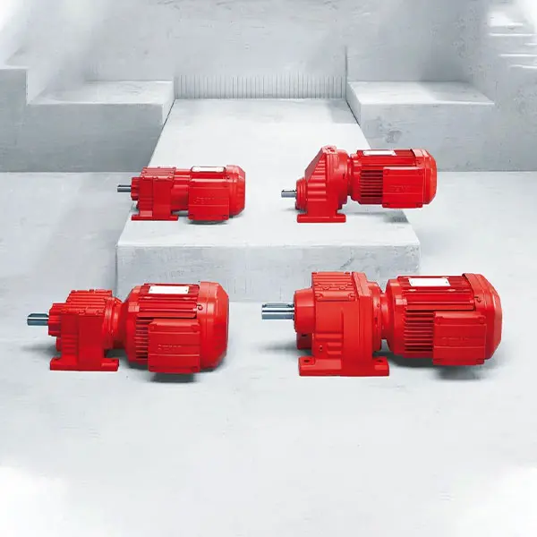 R Series Helical Gearmotor low voltage
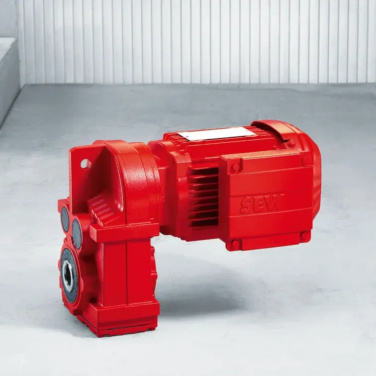 F Series Parallel Shaft Gearmotor low voltage
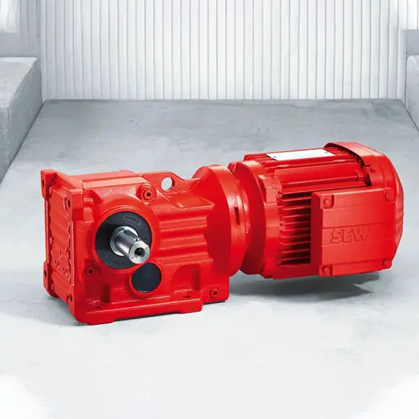 K Series Helical Bevel Gearmotor low voltage
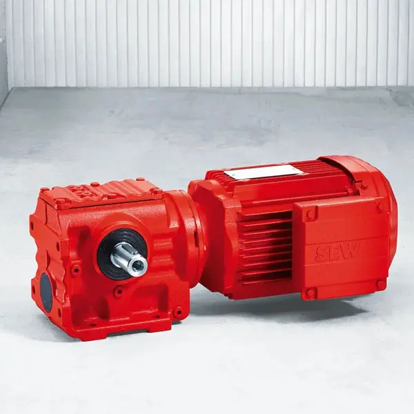 S Series Helical Worm Gearmotor low voltage
 W Series SPIROPLAN® Right Angle Gearmotor
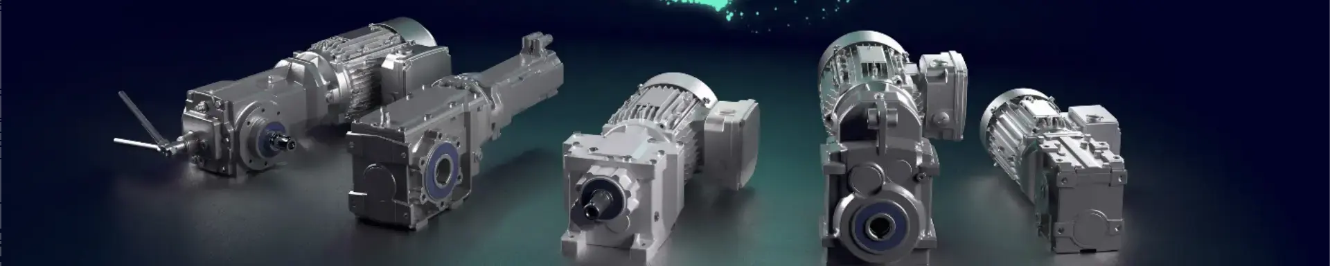
FLENDER Coupling
- SIEMENS Gearmotor
- NORD Industrial Gear Unit
- LENZE Gearmotor
- NORD Gearmotor
- SEW Planetary Gear Unit
- SEW Industrial Gear Unit
- SEW Gearmotor
- BONFIGLIOLI Precision Planetary Gearbox and Gearmotor
- BONFIGLIOLI Inverters and Servo drives
- BONFIGLIOLI Industrial Gear Unit
- BONFIGLIOLI Gearmotor
- FLENDER Coupling
- FLENDER Gear Unit
01

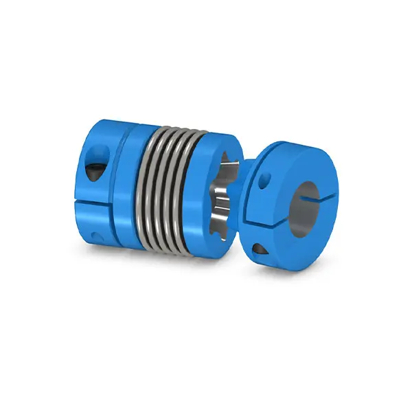
SIPEX Backlash free Coupling high performance
Benefits
SIPEX couplings are suitable for mounting horizontally, vertically or in any desired position. The coupling parts can be arranged as required on the shaft ends to be connected.
The metal bellows are very torsional-resistant and combined with different clamping connections they ensure an absolutely angle-preserving torque transmission between the connected shafts. The moment of inertia is low.
SIPEX couplings compensate axial, radial and angular shaft misalignment with only low restoring forces. SIPEX couplings are wear-free within their technical limits and therefore offer an unlimited service life.
Application
SIPEX couplings are available in 19 sizes within the standard catalog range, 7 of which are miniature versions and the other 12 standard designs. Rated torques range from 0.1 to 5000 Nm. The coupling is suitable for ambient temperatures of between -30 °C to +120 °C.
Couplings manufactured by alternative methods are available for higher ambient temperatures up to +250 °C.
SIPEX couplings from the standard range are especially suitable for application in highly dynamic drives such as, for example, linear axes in machine tools, packaging machines or printing presses, or generally for automation technology.
SIPEX couplings from the miniature range are designed for use in combination with rotary encoders, stepper motors or tachometers.
Design and configurations
SIPEX couplings consist of two hub parts that are connected by means of bellows made of high-strength stainless steel.
The hubs can be coupled to the shafts by many different methods including set screws, key joint, slotted clamping hubs, halfshell hubs, clamping hubs or expanding hubs.
Thanks to their metal bellows, SIPEX couplings are torsionally rigid, but flexible. Misalignment between the connected shafts deforms the metal bellows.
Coupling materials
Depending on the coupling version, hubs are made of aluminum (N, G, H) or steel (K, I), but stainless-steel variants are also optionally available.
All the metal bellows are made of stainless steel and are available as single-wall or multiple-wall devices depending on size and application. Metal bellows come in various standard lengths.
Metal bellows can be combined with different hub versions to create a complete unit. Once the hubs have been joined to metal bellows, they cannot be dismantled again.
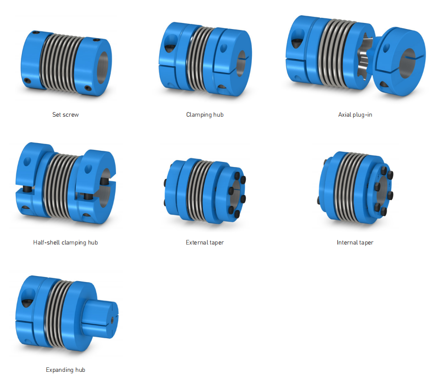
Hub versions
Hub Description
N Hub with set screws
G Slotted clamping hub
H Half-shell clamping hub
K Clamping hub with external taper
I Clamping hub with internal taper
S Expanding hub
Hubs are supplied as standard with bore tolerance H7 and without keyway.
Versions N, G and H are optionally available with keyway in accordance with DIN 6885-1.
The fitting tolerance of the coupled shaft ends should be g6 or h7.
Versions of SIPEX couplings
Type Description
SNN Hub with set screw on both sides
SGG Slotted clamping hub on both sides
SGG-A Slotted clamping hub - for axial plug-in
SHH Half-shell clamping hub on both sides
SKK Clamping hub with external taper on both sides
SHH-W Drive shaft with half-shell clamping hubs
SII Clamping hubs with internal taper on both sides
SGS Hub 1: Slotted, Hub 2: Expanding hub
Coupling dimensioning
Dimensioning according to torque
It must be ensured that the coupling is capable of safely transferring peak torques that regularly occur at the drive or load end. The service factor is provided in order to describe the deviation between the real coupling load and
ideal load conditions:
TKN ≥ TAS ⋅ FB or TLS ⋅ FB
Torque characteristic of drive Service factor FB
Uniform 1.5
Non Uniform 2
Rough 2.5 - 4
Servomotors (machine tools) 1.5 - 2
Dimensioning according to acceleration torques
The correct coupling size can be calculated more accurately on the basis of acceleration or deceleration torques because the peak torque at the coupling is reduced by the ratio between the moments of inertia on the drive and load ends:
Coupling dimensioning
Checking the maximum torsion angle
If the application requires a maximum torsion angle of the coupling, the selected coupling size must be checked to ensure that it is sufficiently torsionally rigid for the application in question:
Checking the maximum speed
For all load situations nKmax > nmax
Checking the permitted shaft misalignment
The actual shaft misalignment must be less than the permitted shaft misalignment for all load situations.
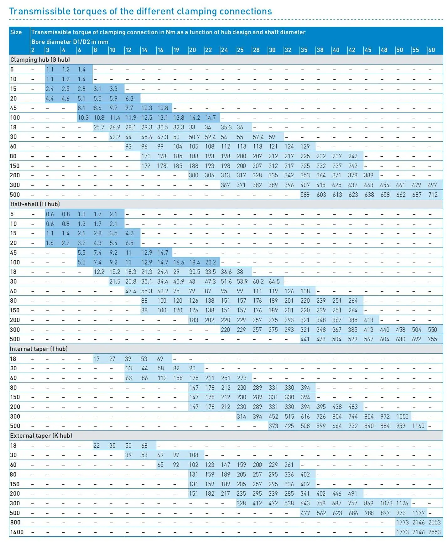
Checking the shaft-hub connection
In the case of clamping connections without feather key, it must be ensured that the transmissible torque of the hub connection is greater than the peak torque at the coupling.
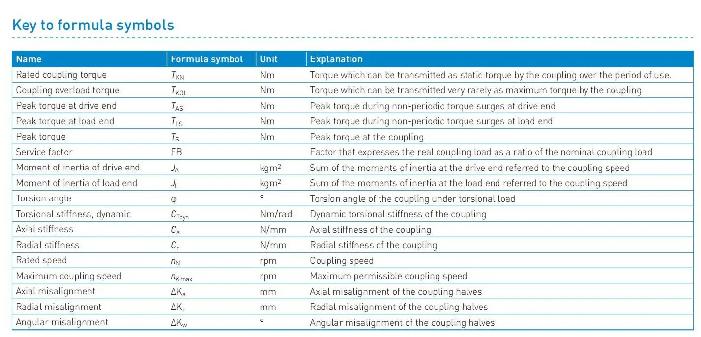
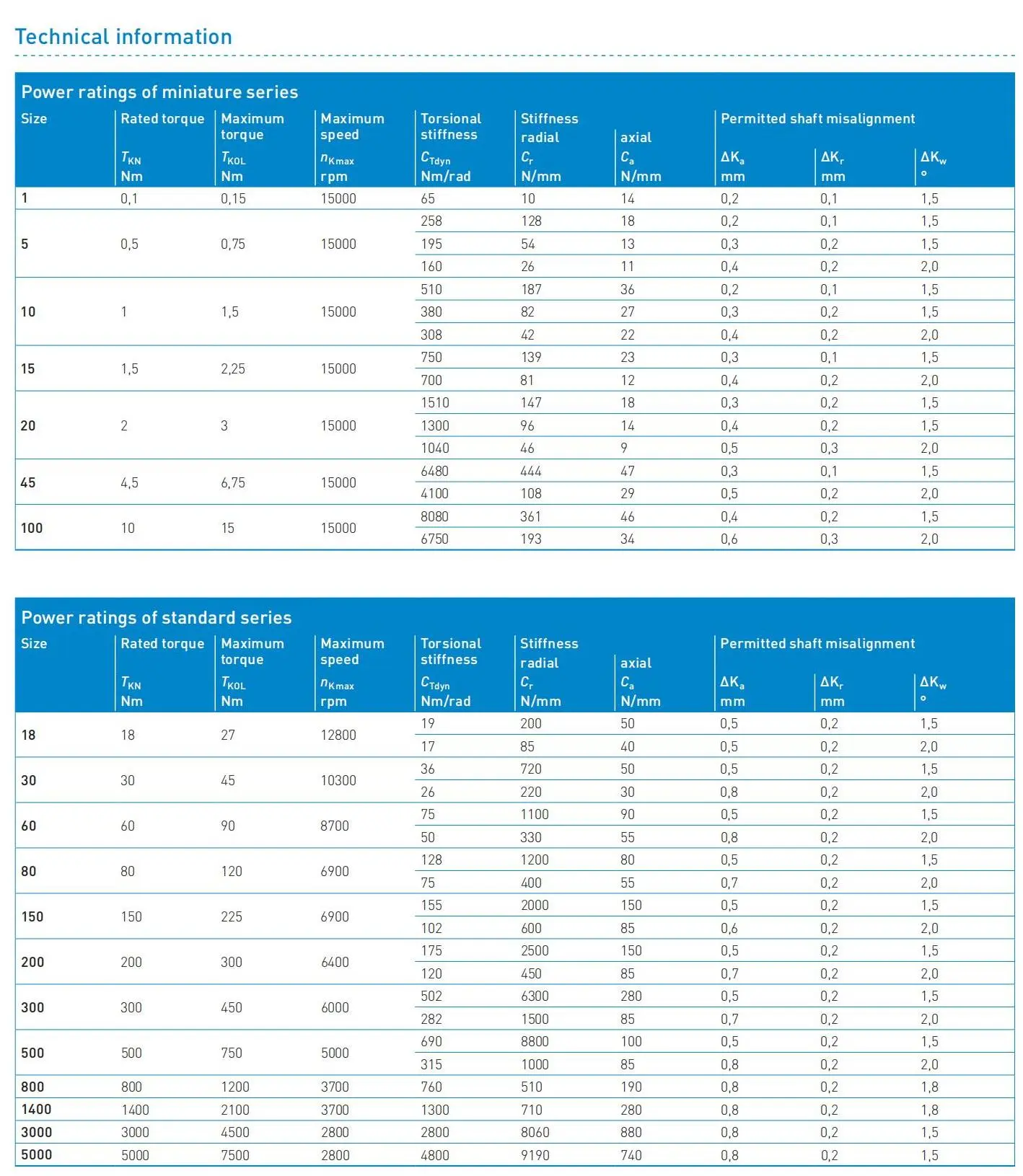
Technical information