Why Choose Gear Flender Couplings for Industrial Use?
In heavy industry, a coupling is easy to overlook until a drive train starts vibrating or a production line stops. A Gearflendercoupling can connect shafts while transmitting high torque in demanding applications, including pumps, mills, and conveyors. Its toothed design can accommodate limited angular and parallel misalignment, but it cannot correct poor alignment or careless installation. Small details matter.
For an illustrative expert perspective, fictional maintenance engineer Daniel Reed puts the trade-off this way: “A strong coupling still depends on alignment, lubrication, and regular inspection.” This is a representative statement, not a verified quotation from a real specialist. In practice, technicians check tooth wear, seals, lubricant condition, and operating temperature. A grease leak near the coupling guard, for example, may signal a maintenance issue worth investigating. Not every vibration starts there.
Why choose this coupling type? Its compact construction and torque capacity can suit applications where space is limited and loads are substantial. Selection still requires checking torque, speed, shaft dimensions, service factors, and the manufacturer’s limits. The right model depends on the actual machine, not just its nameplate rating. Installation quality matters, too. Even a well-specified unit may underperform if alignment, lubrication, or inspection intervals are neglected. This introduction examines those practical trade-offs, so readers can assess where gear couplings fit—and where another coupling design may be more appropriate.
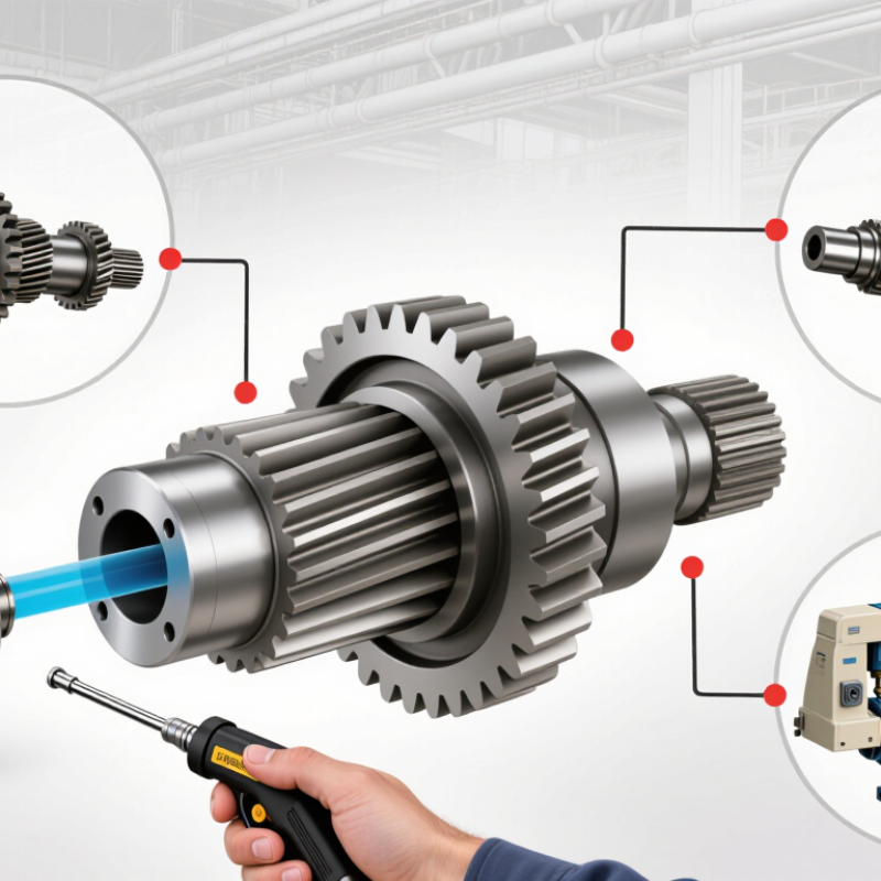
What Is a Gear Flender Coupling?
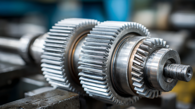
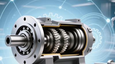
A gear coupling is a mechanical connection that transfers torque between two rotating shafts. It typically uses two toothed hubs, one mounted on each shaft, that mesh with internally toothed sleeves. The teeth allow limited angular, parallel, and axial movement while maintaining power transmission. This makes the coupling useful in demanding equipment such as pumps, compressors, and conveyors. The exact misalignment limits depend on the coupling’s design, speed, and load. Not maintenance-free.
Lubrication is essential: inadequate or degraded lubricant can accelerate tooth wear, especially where machinery runs under heavy loads or frequent starts. The U.S. Department of Energy’s Improving Pumping System Performance: A Sourcebook for Industry reports that pumping systems use nearly 20% of global electrical energy and can account for 25–50% of energy use in some industrial facilities. That figure does not measure coupling performance, but it highlights why reliable shaft connections matter. In practice, technicians should check alignment, lubricant condition, and tooth wear during scheduled inspections. A coupling can accommodate some misalignment; it cannot correct poor installation. That distinction is easy to miss.
Why Choose Gear Couplings for Industrial Use? – What Is a Gear Coupling?
| Dimension |
Description |
Industrial Relevance |
| What it is |
A flexible mechanical coupling that connects two rotating shafts and transmits torque through meshing gear teeth. |
Provides a compact connection between a driver, such as a motor, and driven equipment. |
| Typical construction |
Common designs use two shaft-mounted hubs with external teeth engaging internally toothed sleeves. Designs and component arrangements vary. |
The tooth engagement transfers torque while allowing limited relative movement between connected shafts. |
| Torque transmission |
Torque is carried by the meshing teeth. Capacity depends on factors such as coupling size, materials, speed, lubrication, and operating conditions. |
Can suit demanding drives, provided the selected coupling is rated for the actual load and service conditions. |
| Misalignment accommodation |
Many designs accommodate limited angular, parallel, and axial misalignment within their specified limits. |
Does not eliminate the need for proper shaft alignment; excessive misalignment can increase wear and loads on connected equipment. |
| Lubrication and maintenance |
Tooth contact generally requires lubrication. The lubricant type, replenishment interval, and sealing requirements depend on the design and operating conditions. |
Regular inspection for lubricant condition, leakage, wear, and alignment helps support reliable operation. |
| Common applications |
Used in various rotating drives, including pumps, compressors, conveyors, and industrial processing equipment, when the coupling is correctly specified. |
Selection should account for torque, speed, starting conditions, alignment, environment, and maintenance access. |
| Key selection checks |
Verify shaft and bore dimensions, rated torque and speed, misalignment limits, lubricant requirements, environmental conditions, and applicable safety requirements. |
Use the selected model’s technical documentation and the equipment manufacturer’s requirements rather than relying on a generic rating. |
How Does a Gear Coupling Transfer Torque?
A gear coupling transfers torque through meshing teeth. Each shaft carries a hub with external teeth, while an internally toothed sleeve connects the hubs. As the driving shaft turns, its teeth push against the sleeve teeth. The sleeve then drives the second hub and shaft. Torque passes through tooth contact, not through friction alone.
The U.S. Department of Energy’s 2021 Industrial and Commercial Motor System Market Assessment estimates that motor-driven systems use about 68% of U.S. manufacturing electricity. That figure does not measure coupling performance, but it shows why dependable power transmission matters. In practice, technicians check tooth wear, lubricant condition, and shaft alignment. A small angular offset can be accommodated by crowned teeth, while excessive misalignment increases edge loading and heat. Details matter.
Grease or oil separates the contacting teeth and helps limit wear. Yet lubrication cannot fix poor alignment. A coupling may tolerate slight shaft movement, but its actual limits depend on its size, speed, and load. Check the maker’s specifications. And inspect it. One overlooked detail is axial movement: a coupling needs enough clearance for expected shaft travel. I would not assume that a unit running quietly is healthy; early tooth wear can be easy to miss.
Why Choose Gear Couplings for Industrial Use?
How Does a Gear Coupling Transfer Torque?
A gear coupling transfers torque through meshing teeth on its hubs and sleeve. Their tooth engagement carries rotational force between connected shafts, while the coupling design can accommodate limited misalignment. This chart shows theoretical shaft torque at constant power, calculated using T (N·m) = 9,550 × P (kW) ÷ speed (rpm); it does not represent a coupling’s rated capacity.
Which Industrial Conditions Suit Gear Flender Couplings?
Gear couplings suit industrial drives that need to transmit high torque through a compact connection. They are often considered for conveyors, mixers, pumps, and rolling equipment with steady, demanding loads. A gearbox output shaft and driven machine may not stay perfectly aligned as temperatures change or foundations settle. The coupling can accommodate limited misalignment, but it cannot fix poor installation. Alignment still matters.
These couplings are a practical choice where equipment runs for long shifts and planned lubrication checks are possible. Dust, moisture, and heat can affect seals and lubricant, so the surrounding conditions and maintenance schedule should guide selection. Check the required torque, speed, shaft dimensions, and allowable misalignment against the coupling specification. Keep access for inspection in mind. That detail is easy to overlook. Gear couplings may be less suitable where maintenance access is restricted or lubrication is difficult. Even a robust design can wear early if it runs dry or outside its rated limits. Industrial service is rarely perfectly predictable, so leave a reasonable operating margin.
What Performance Benefits Can These Couplings Provide?
Gear-type couplings transmit high torque through meshing teeth, making them useful on pumps, compressors, and conveyors with demanding start-up loads. Their compact design can fit between closely spaced shafts. They also tolerate limited angular and parallel misalignment, which helps when thermal growth shifts equipment during operation. Not a cure for poor alignment.
A U.S. Department of Energy industrial motor systems assessment reported that motor-driven systems use about 68% of electricity consumed in U.S. manufacturing. This is a system-wide figure, not a claim that couplings alone deliver energy savings. Still, reducing avoidable vibration and shaft loading can support steadier operation. In practice, technicians should check tooth wear, lubrication, and alignment; a dry, worn coupling can turn a robust drive into a noisy one.
The performance benefit is practical: reliable torque transfer under variable loads, with less sensitivity to small installation errors than rigid connections. Gear couplings can also accommodate modest axial movement, depending on their design. However, they need regular inspection and correct lubrication. That maintenance is easy to postpone. A small inspection window, fresh lubricant, and recorded vibration readings can reveal trouble before a coupling overheats or damages connected bearings.
How Should You Select and Maintain a Gear Flender Coupling?
Select a gear coupling from measured operating conditions, not shaft diameter alone. Record continuous and peak torque, startup frequency, speed, bore size, and expected angular, parallel, and axial movement. Leave margin. Too little capacity risks tooth damage; excessive sizing can increase inertia and complicate alignment. Check the service factor against the driven load, temperature, shock, and daily operating hours. The U.S. Department of Energy’s 2014 sourcebook, Improving Motor and Drive System Performance, reports a striking figure. Motor-driven systems use about 68% of U.S. manufacturing electricity. That makes efficient transmission and careful upkeep worth attention.
At planned shutdowns, inspect teeth for pitting, scoring, and uneven contact; check seals, fasteners, and lubricant condition. Measure alignment with suitable instruments after installation and whenever bearings or foundations change. Track vibration and coupling temperature against a clean baseline, then investigate rising trends early. Use the specified lubricant and interval; contamination or overfilling can be as harmful as neglect. Keep records. One limitation: visual checks can miss early tooth wear, so consider operating history and vibration readings too. Recheck alignment after thermal changes or a heavy start.

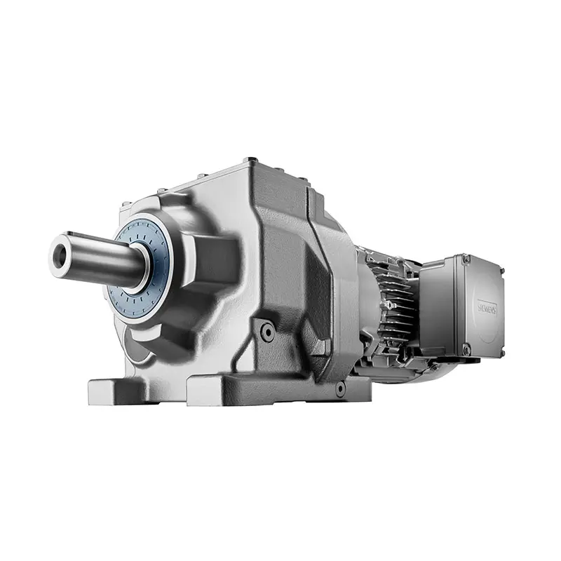 SIEMENS Helical Gearmotor Low Voltage
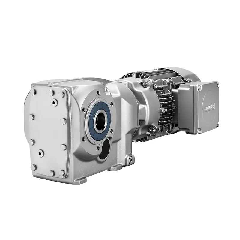 SIEMENS Bevel Helical Gearmotor
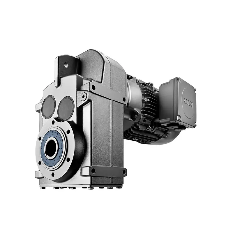 SIEMENS Parallel Shaft Gearmotor
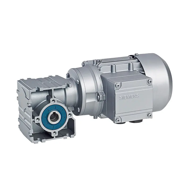 SIEMENS Worm Gearmotor Low Voltage
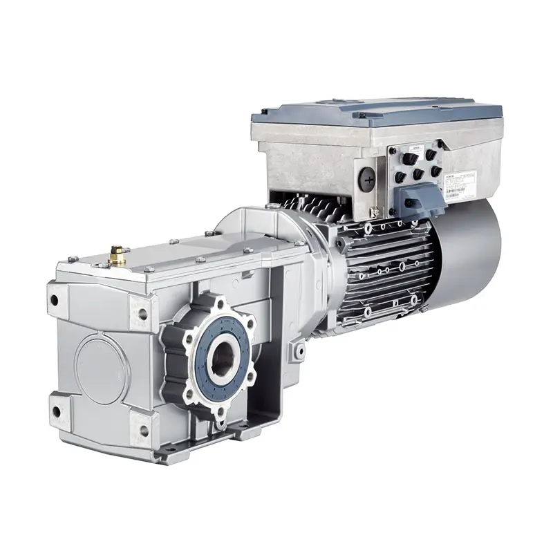 SIEMENS With Servo Motor Gearmotor
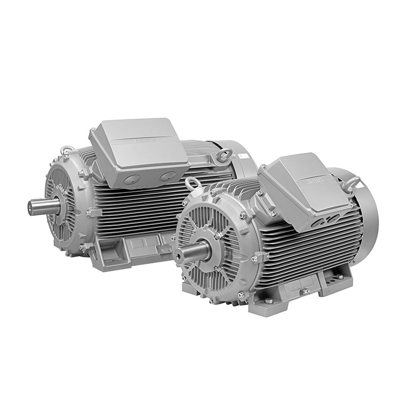 SIEMENS Low Voltage Motor Low Voltage
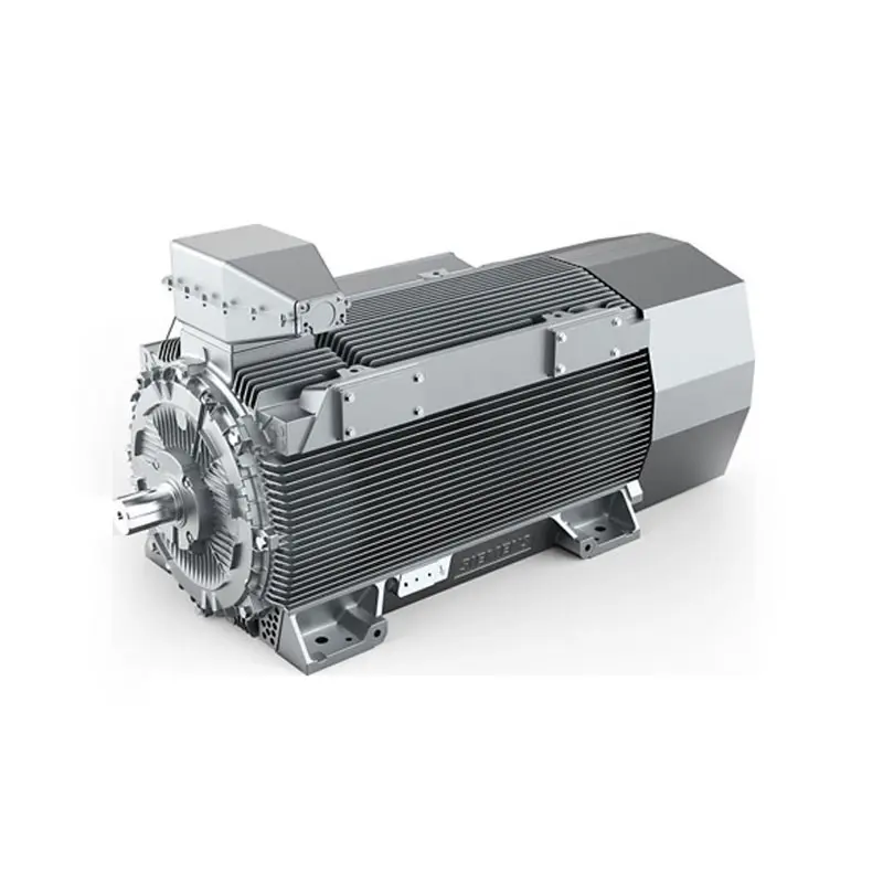 SIEMENS High Voltage Motor Low Voltage
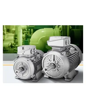 SIEMENS Marine Motor Low Voltage
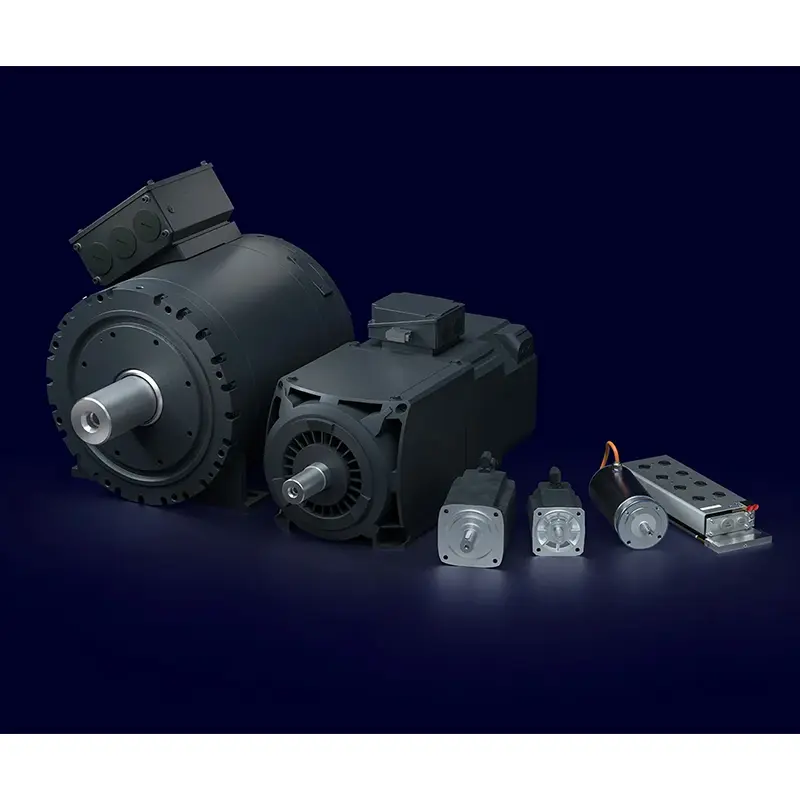 SIEMENS Servo Motor Low Voltage
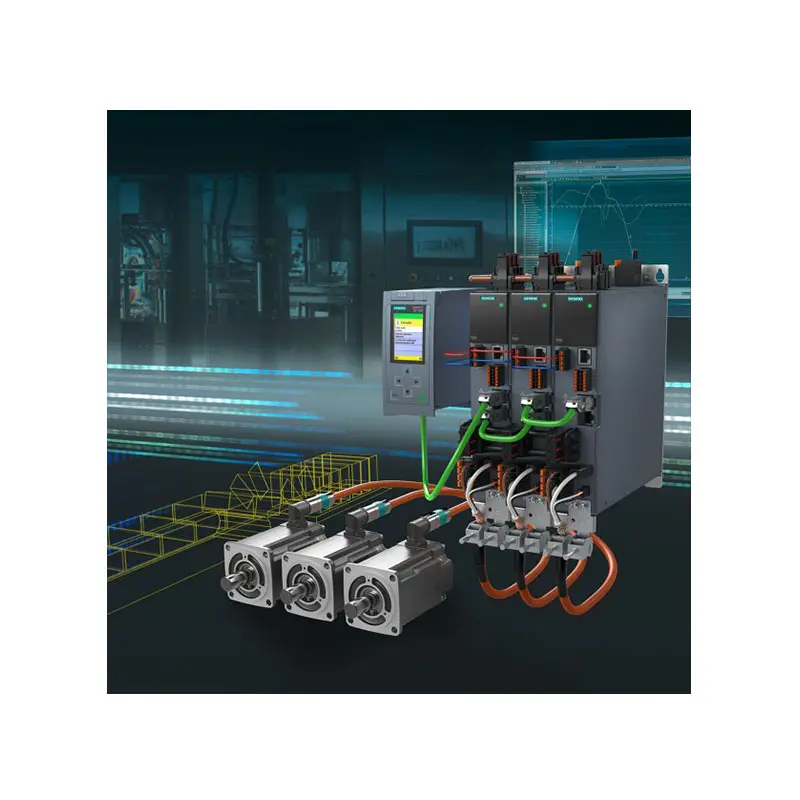 SIEMENS SINAMICS S210 Low Voltage
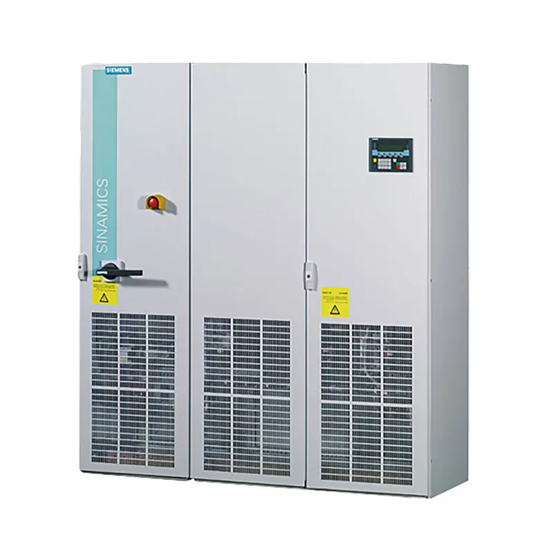 SIEMENS SINAMICS S150 Low Voltage
 SIEMENS SINAMICS S120 Low Voltage
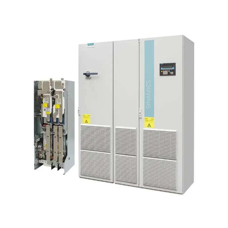 SIEMENS SINAMICS G130/G150
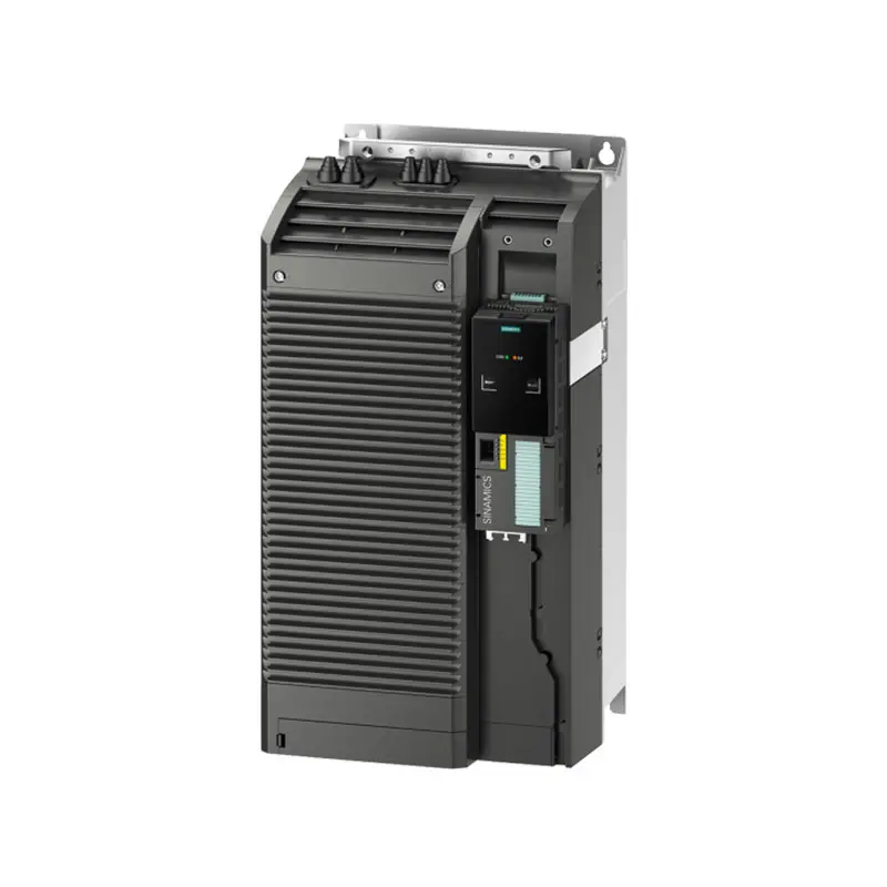 SIEMENS SINAMICS G120 Low Voltage
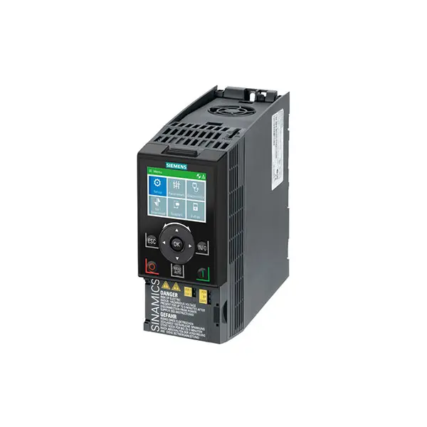 SIEMENS SINAMICS G120C Low Voltage
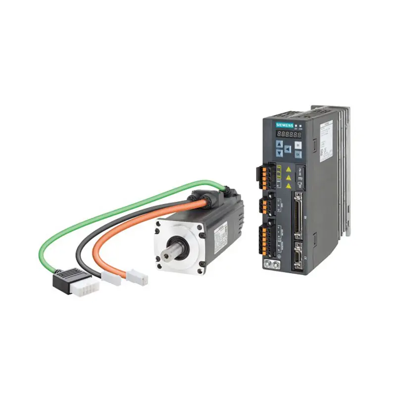 SIEMENS SINAMICS V90
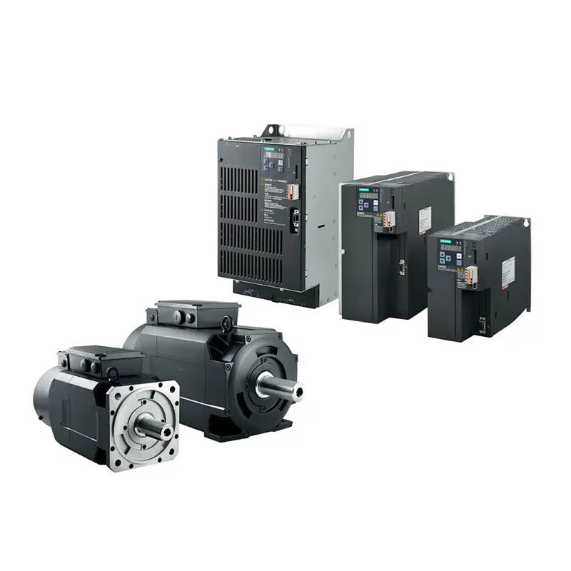 SIEMENS SINAMICS V70 Low Voltage
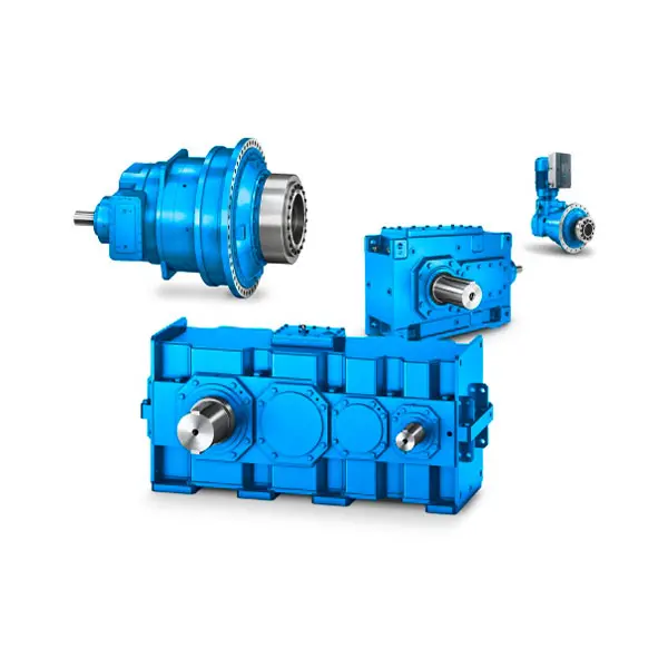 FLENDER Gear Unit
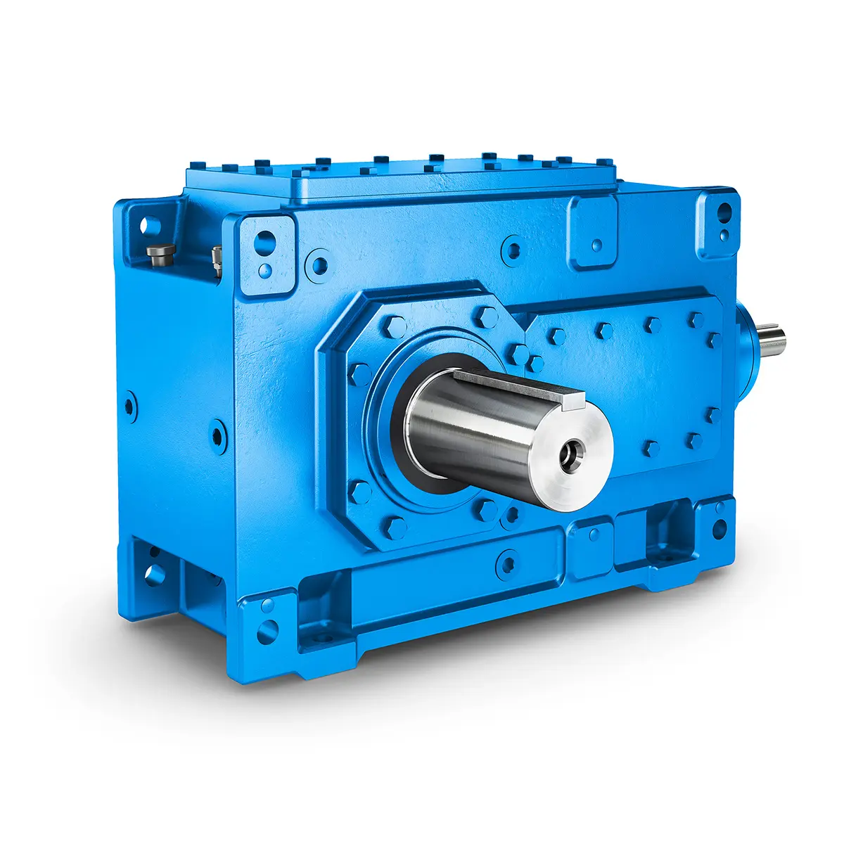 FLENDER Helical Gear Unit
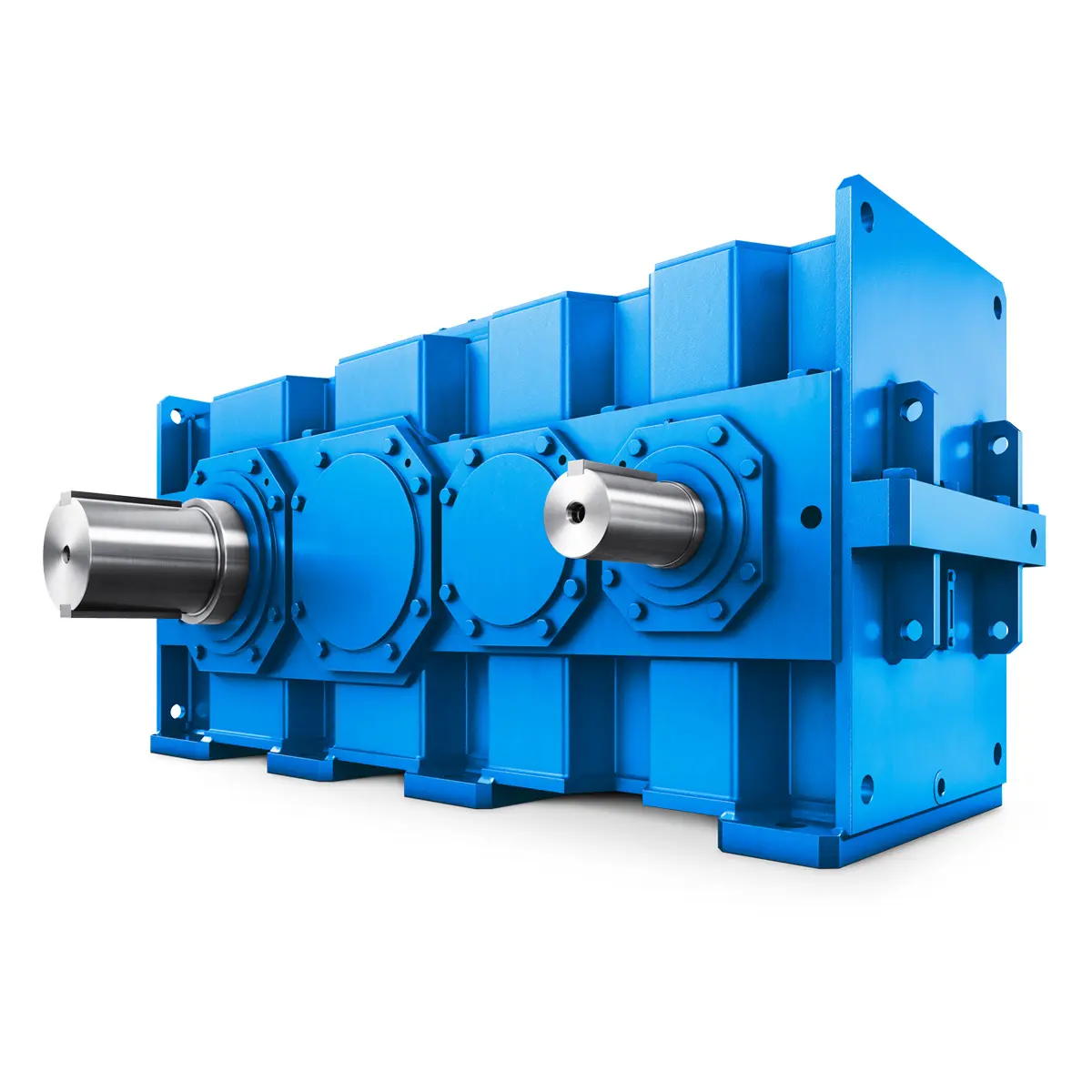 Flender gear units for lifting and luffing gears
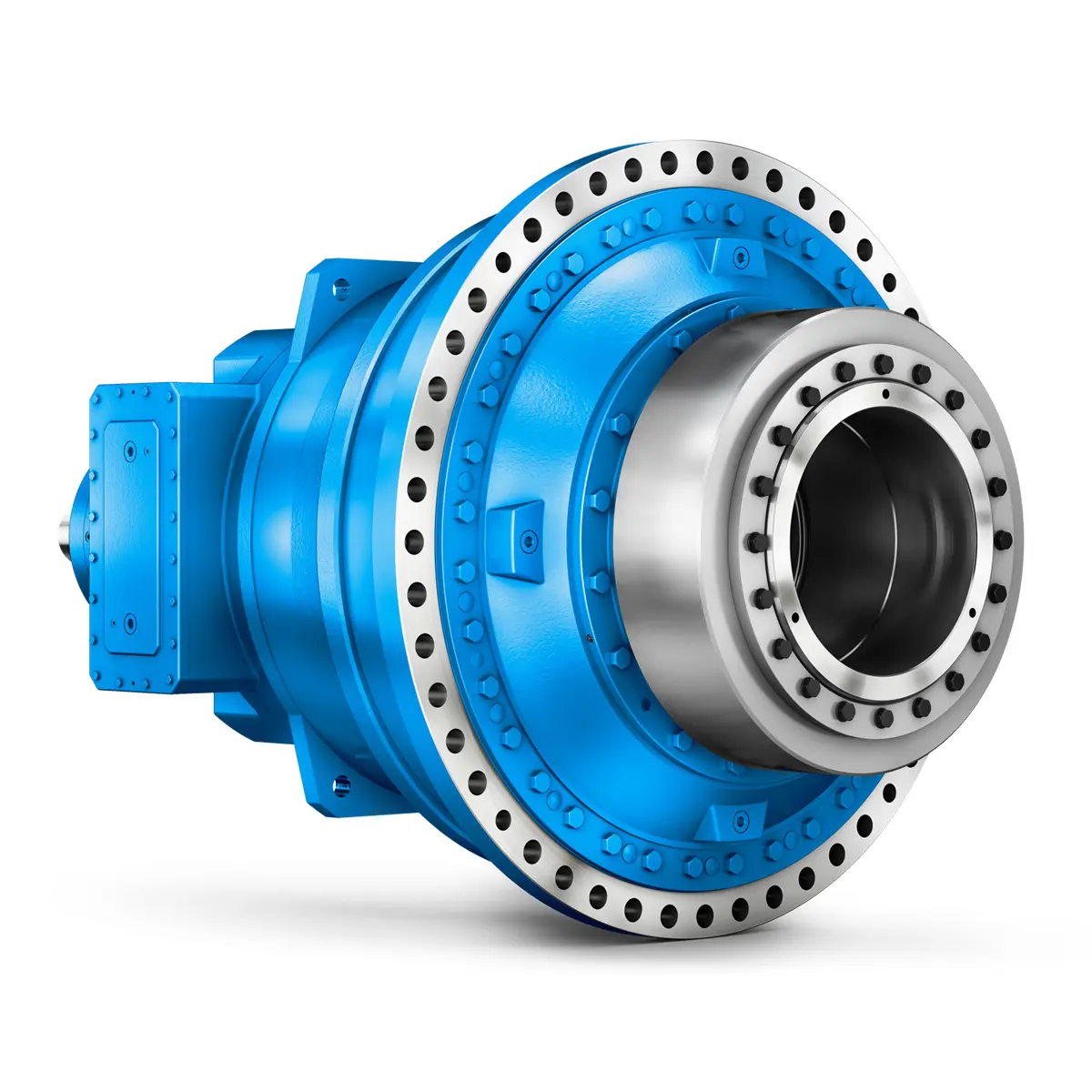 FLENDER Gear Unit gearunit gearbox
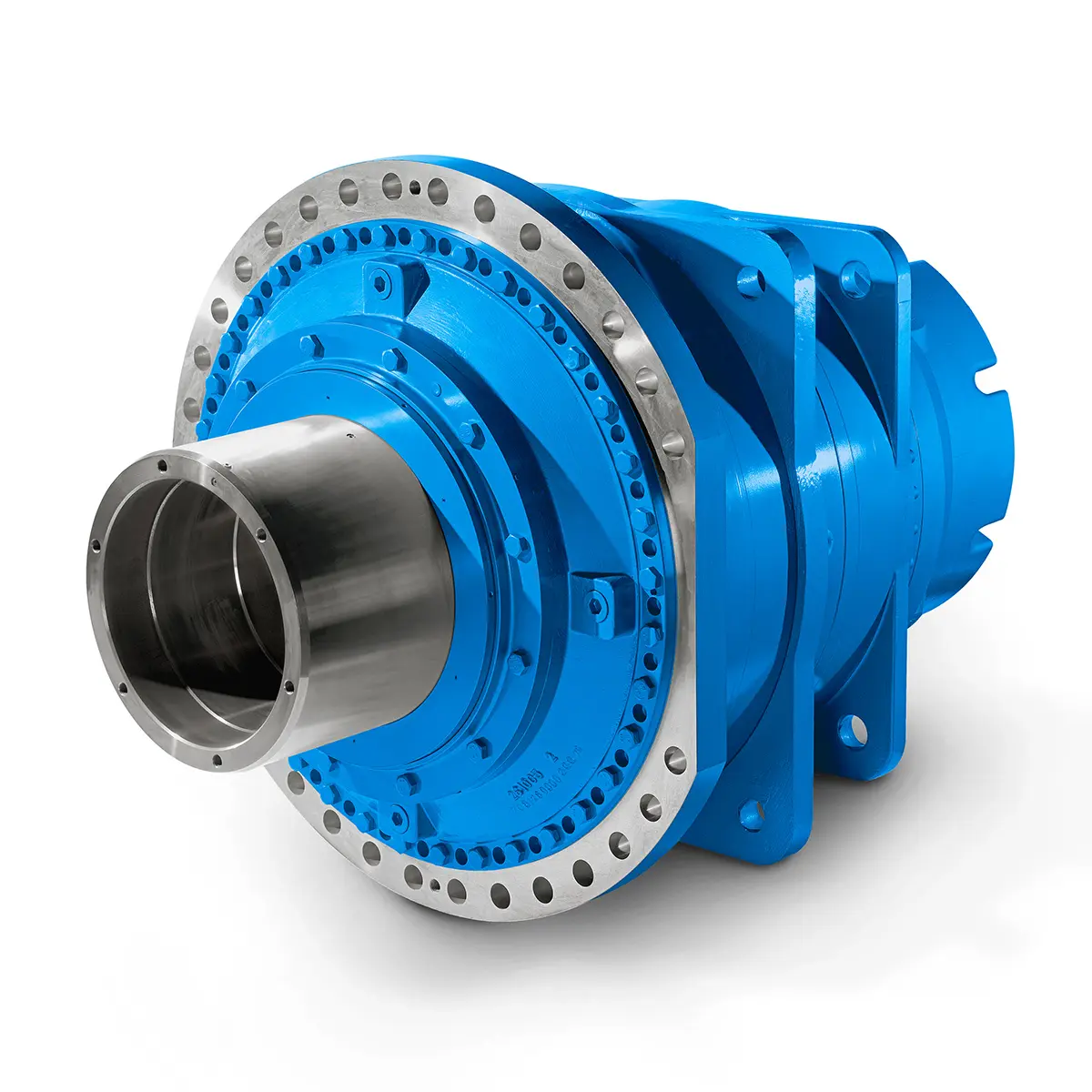 Optimal Drive Solution For Maximum Performance
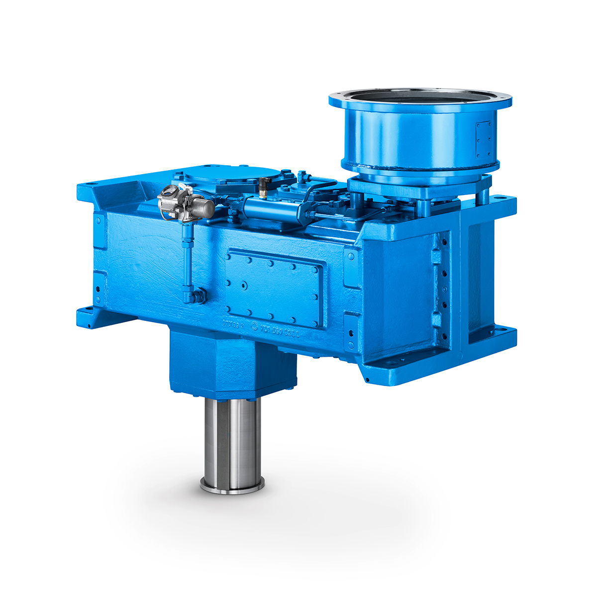 Strongly operating against biodegradable constituents
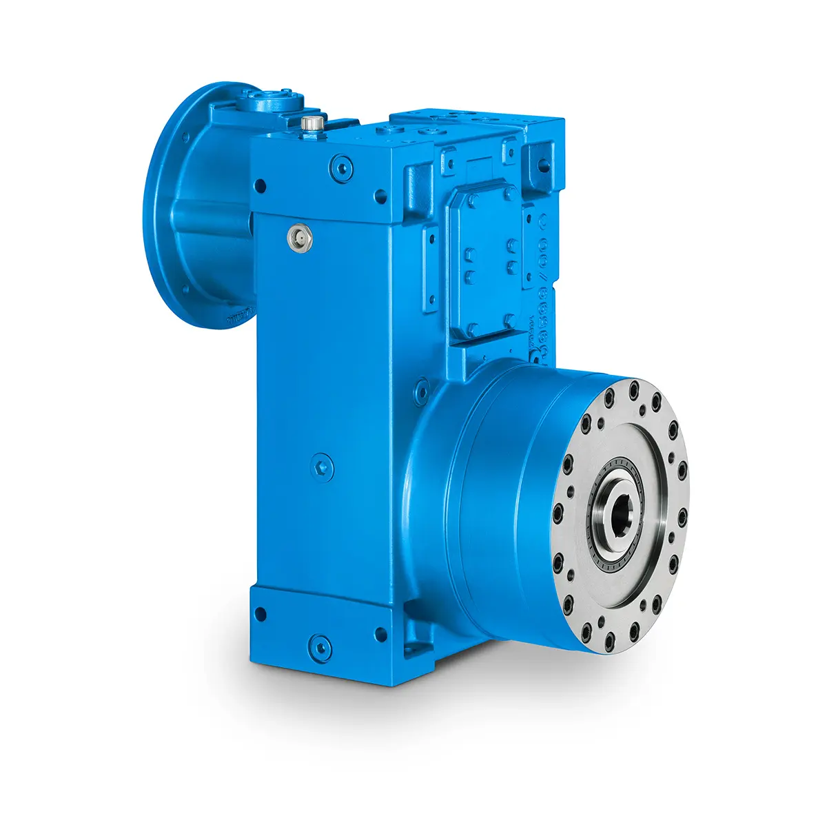 SINGLE SCREW Special industry dedicated gearunit gearbox
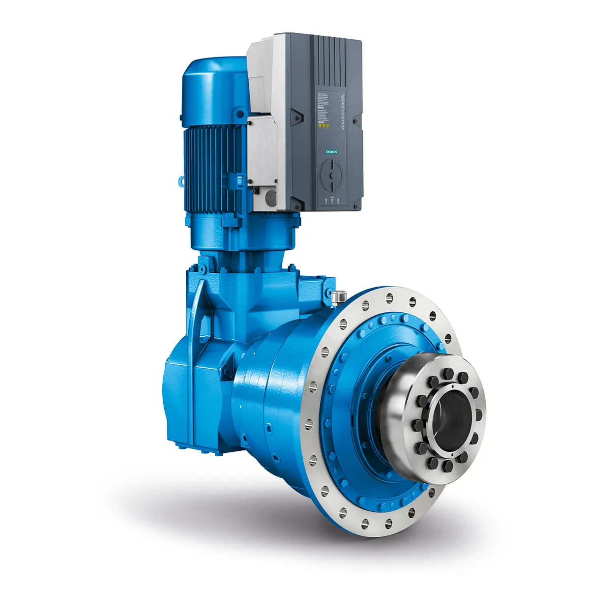 Playmaker In The Premium League
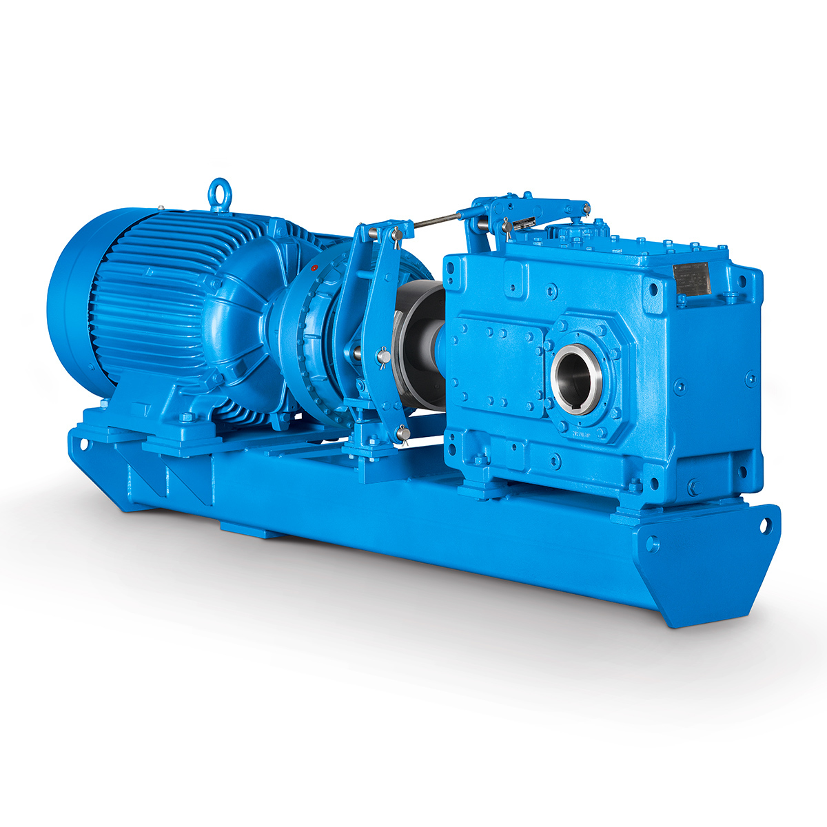 Conveyor belts gearunit gearbox
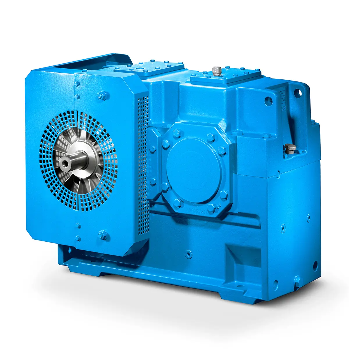 Paper And Pulp Preparation Sections
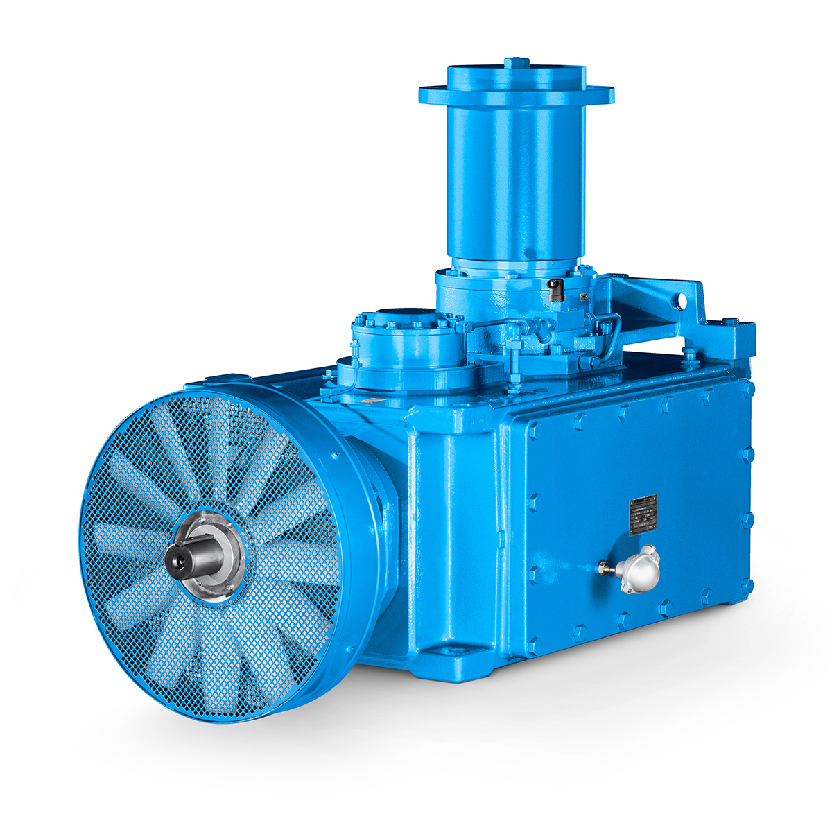 Operational Reliability Even In Case Of The Highest Ventilation Forces
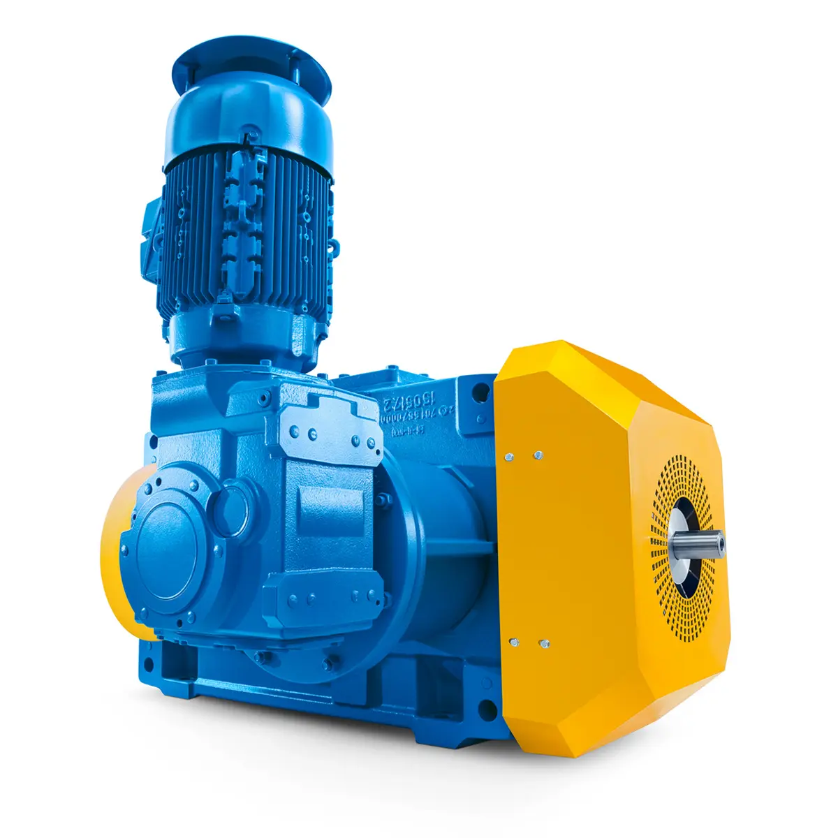 Reliable Gear Units For High Performance Vertical Conveyors 59/200
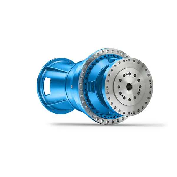 Maximum power density – PLANUREX 3 L individual drives for your sugar cane mill
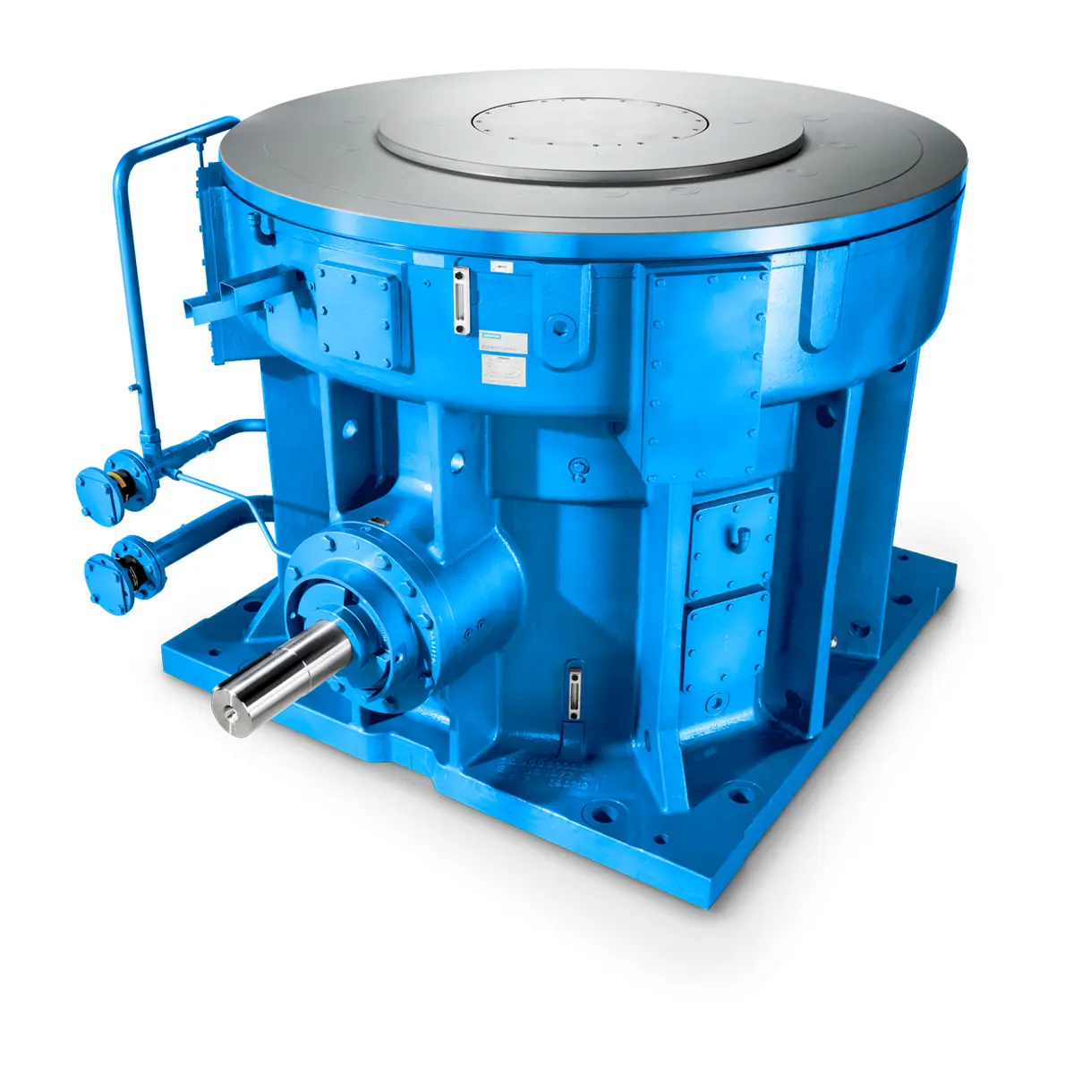 The proven all rounder gearunit gearbox
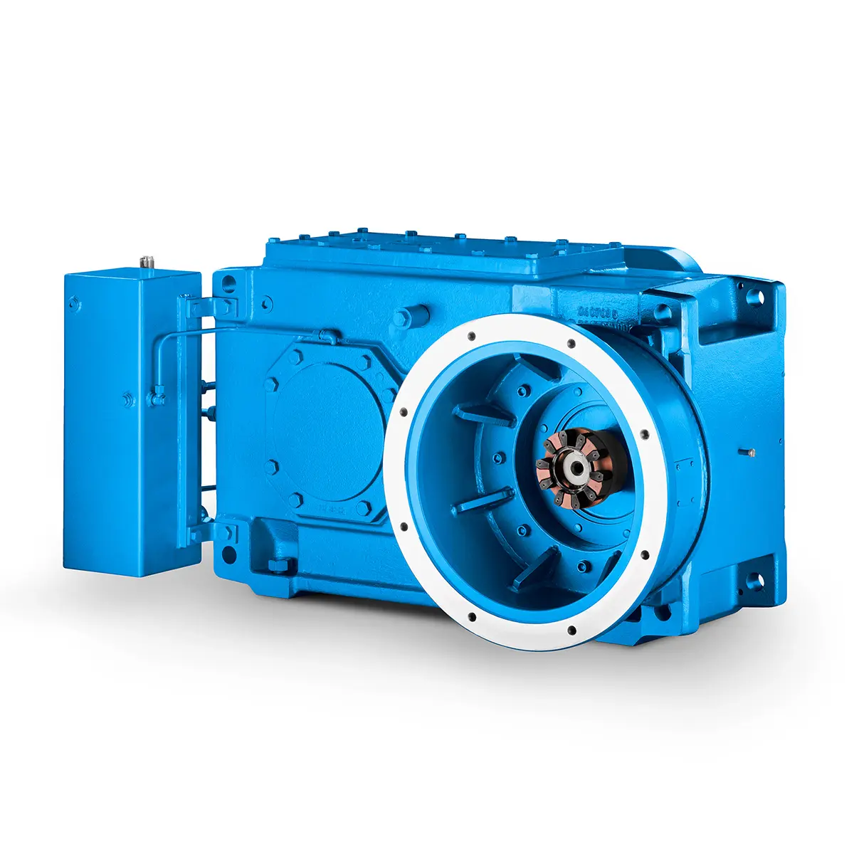 Stirs and stirs and stirs gearunit gearbox
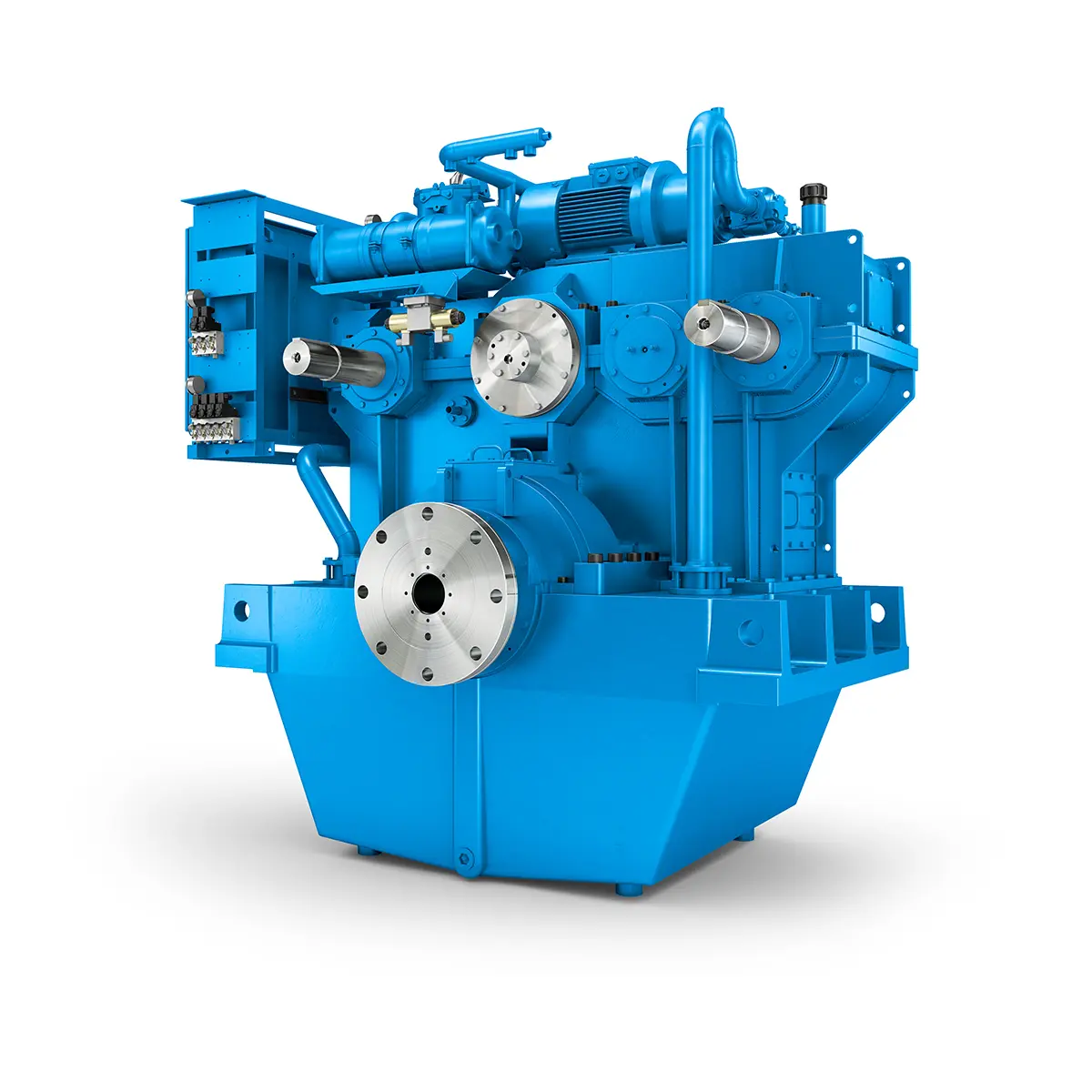 Flexibility on Board gearunit gearbox
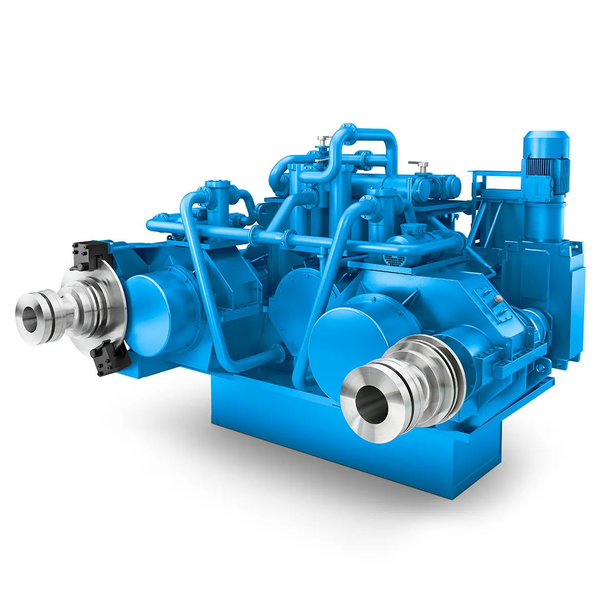 The right gearbox for all Multi-Engine Ships
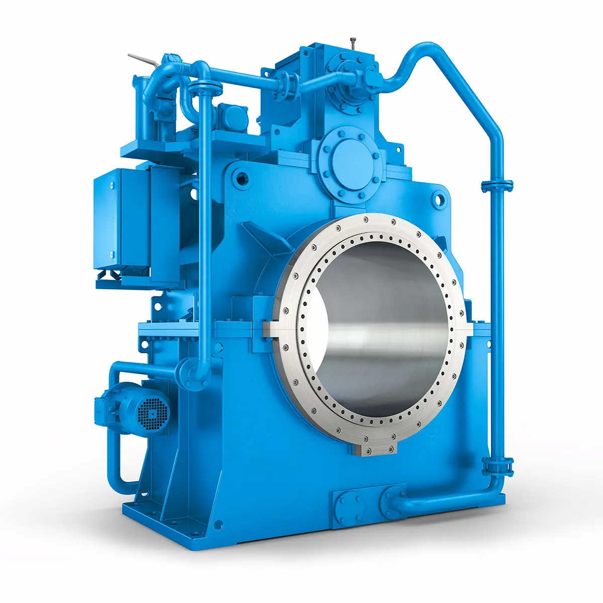 Reliable Power Generation on board
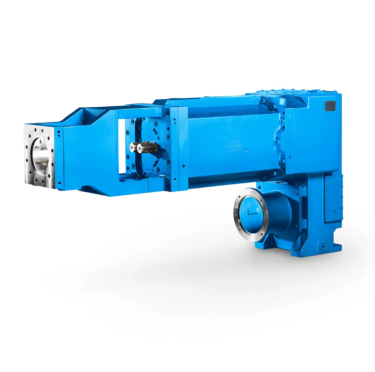 Maximum performance level, fast deliverable
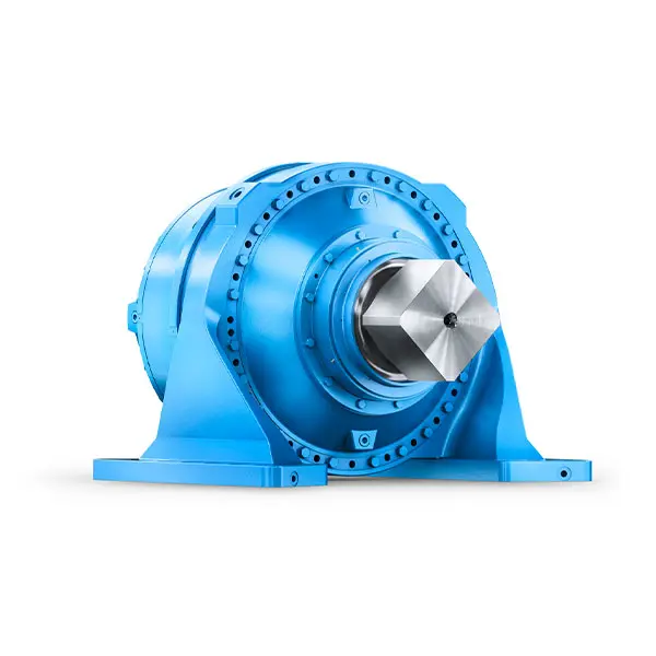 Efficient and compact – FLENDER Gear Units for Sugar Mills
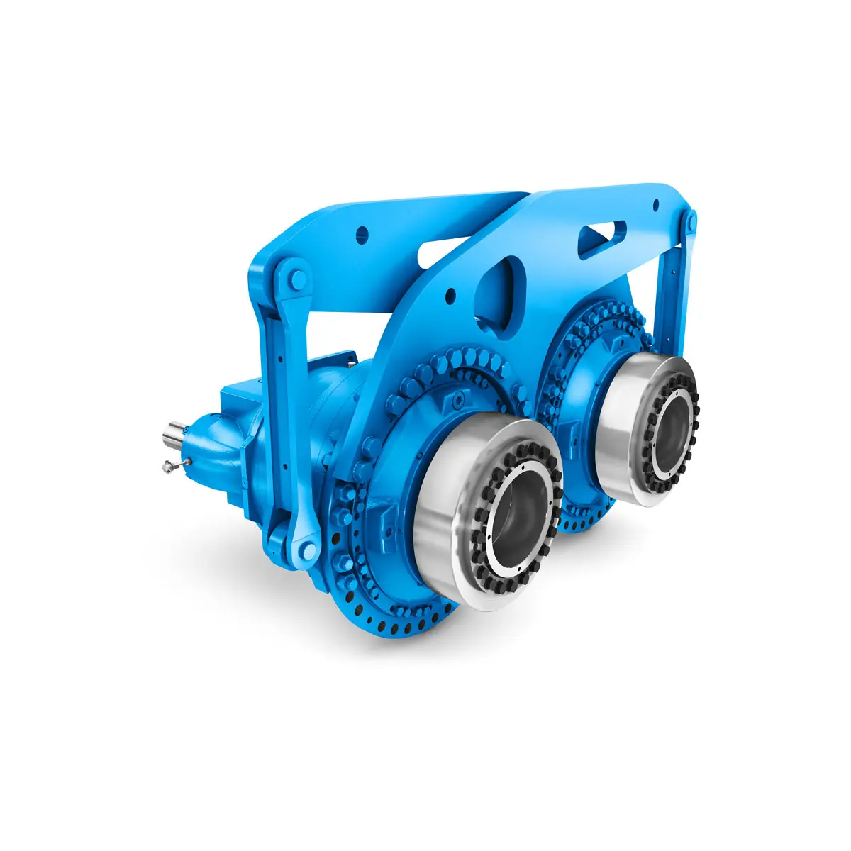 Extremely strong. Extremely compact. Extremely stressable.
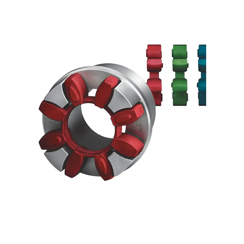 FLENDER Coupling
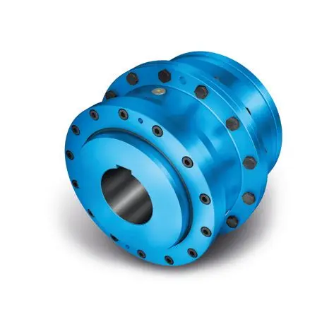 ZAPEX ZW Torsionally Rigid Gear Coupling
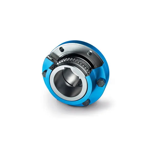 ZAPEX ZN Torsionally Rigid Gear Coupling
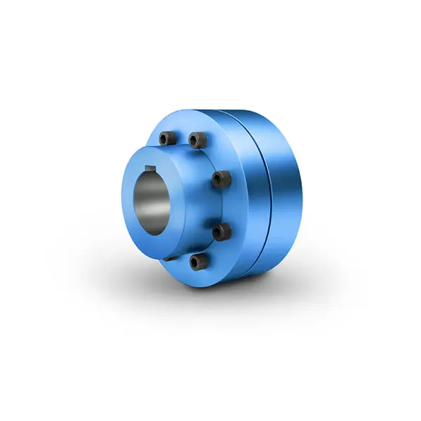 N-EUPEX Flexible high performance Coupling
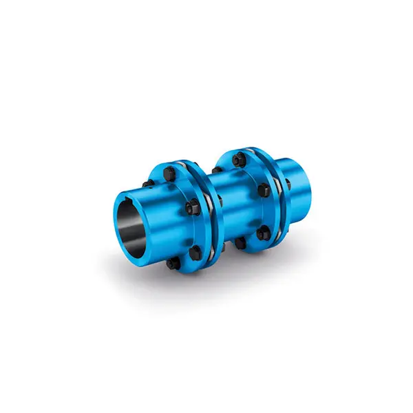 N-ARPEX Torsionally Rigid All-Steel Coupling
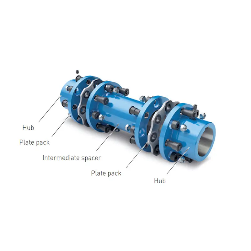 ARPEX Torsionally Rigid All-Steel Coupling Spare and Parts
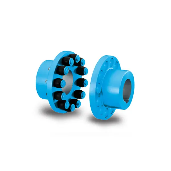 RUPEX Flexible high performance Coupling
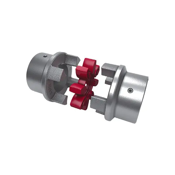 N BIPEX Flexible high performance coupling
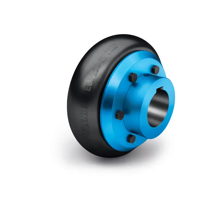 ELPEX B Highly Flexible Coupling
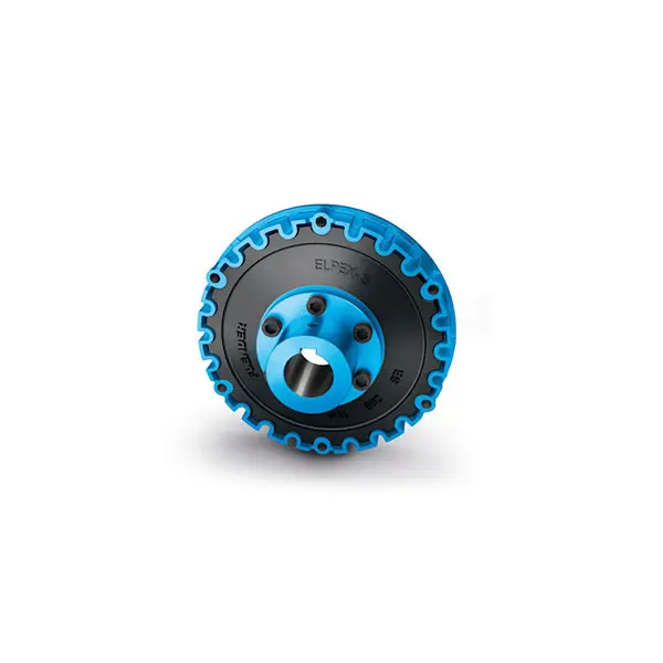 ELPEX S Highly Flexible Coupling high performance
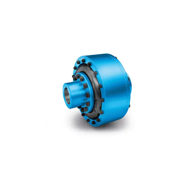 ELPEX Highly Flexible Coupling high performance
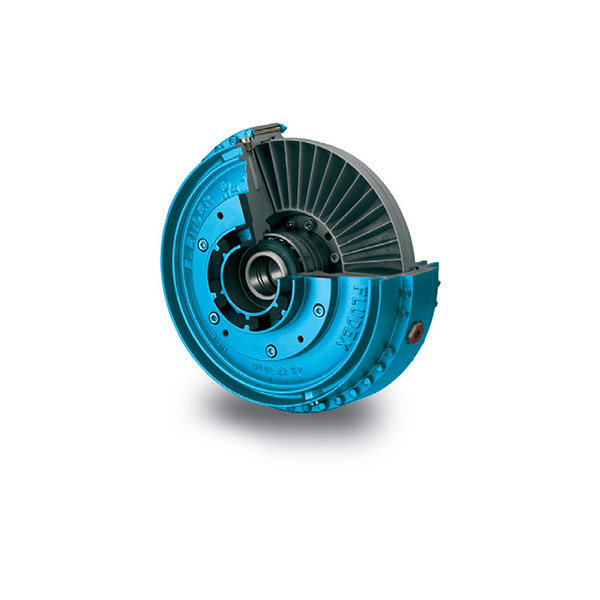 FLUDEX Fluid Coupling high performance
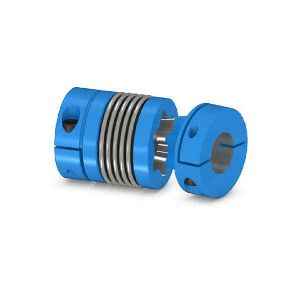 SIPEX Backlash free Coupling high performance
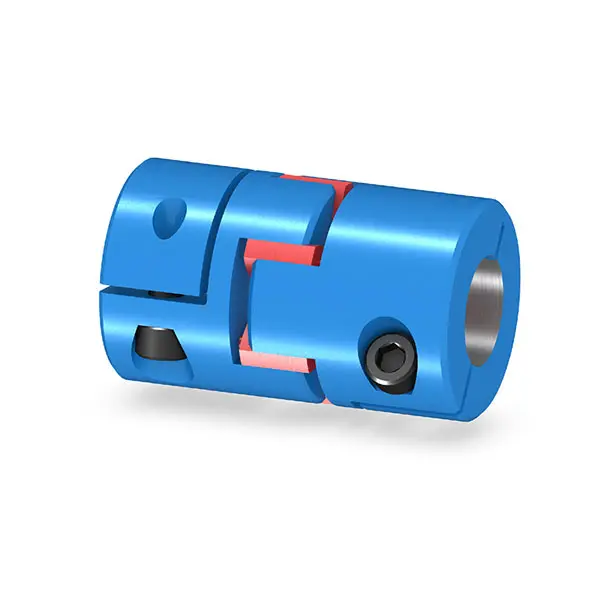 BIPEX S Backlash free Coupling high performance
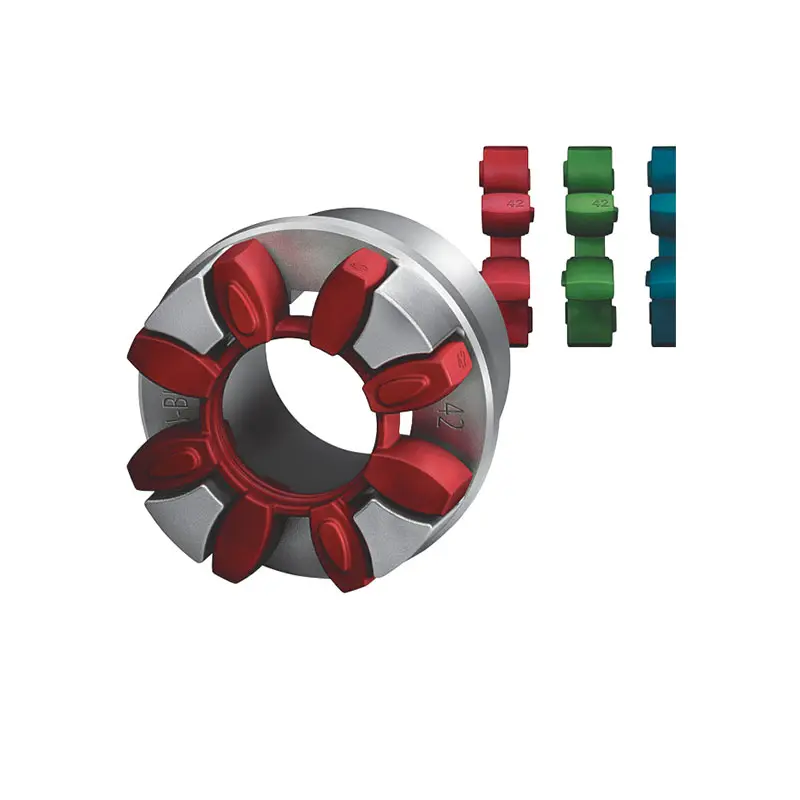 FLENDER Coupling Spare Parts high performance
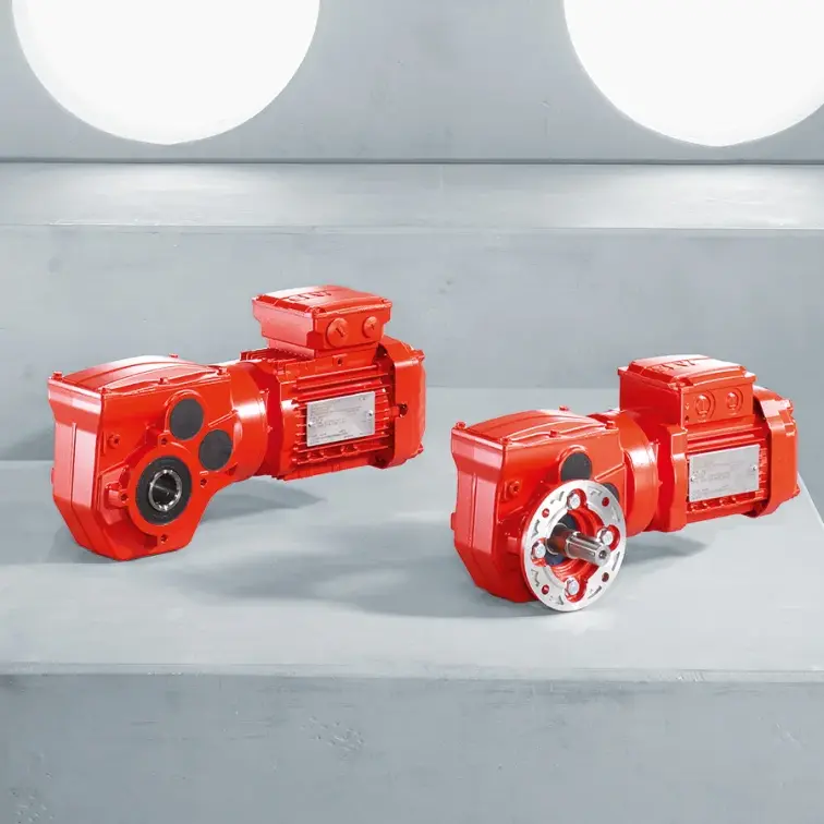 SEW Gearmotor
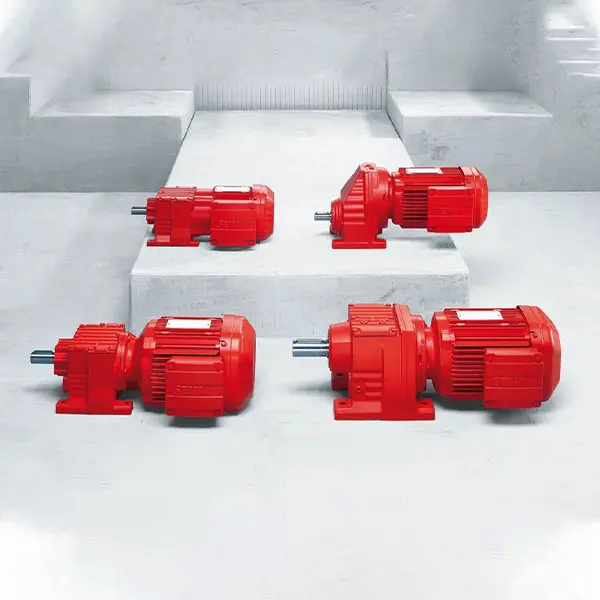 R Series Helical Gearmotor low voltage
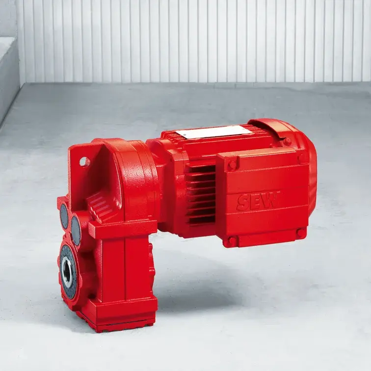 F Series Parallel Shaft Gearmotor low voltage
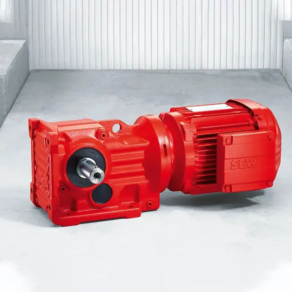 K Series Helical Bevel Gearmotor low voltage
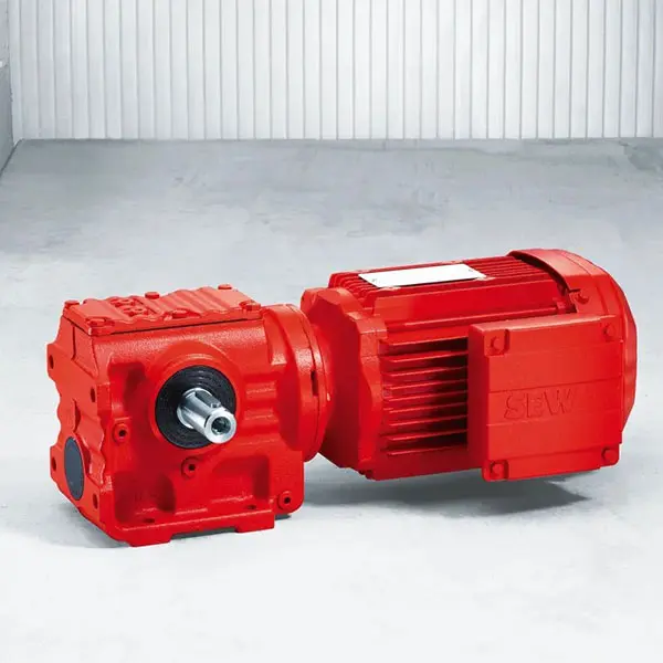 S Series Helical Worm Gearmotor low voltage
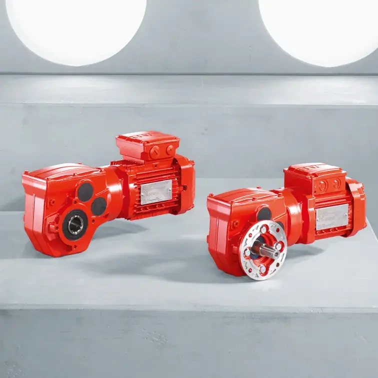 W Series SPIROPLAN® Right Angle Gearmotor